
Esteem GLX Wagon Plus L4-1.6L (1998)
Valve Clearance: Adjustments
1. Remove negative cable at battery.
2. Remove cylinder head cover referring to item Cylinder Head Cover.
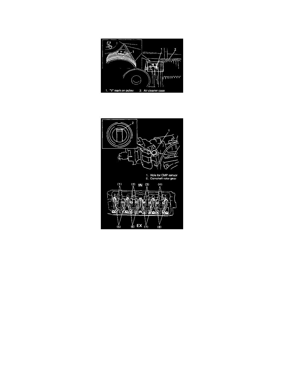
3. Remove right side of engine under cover from body.
4. Open air cleaner upper case and shift case and hose position to observe "V" mark on crankshaft pulley.
5. Using 17 mm socket, turn crankshaft pulley clockwise until "V" mark (in white paint) on pulley aligns with "0" (zero) calibrated on timing belt
cover.
6. Remove Camshaft Position (CMP) sensor and check camshaft rotor gear position. If it is positioned as shown in figure (i.e. No.1 piston is at
(TDC) of compression stroke), check valve lashes at valves (1), (2), (5) and (7).
If it isn't positioned as shown in figure (i.e. it isn't shown in the hole for COP sensor), check valve lashes at valves (3), (4), (6) and (8).
NOTE: When checking valve clearance, insert thickness gauge between camshaft and cam-riding face of rocker arm.