
Esteem GLX Wagon Plus L4-1.8L (1999)
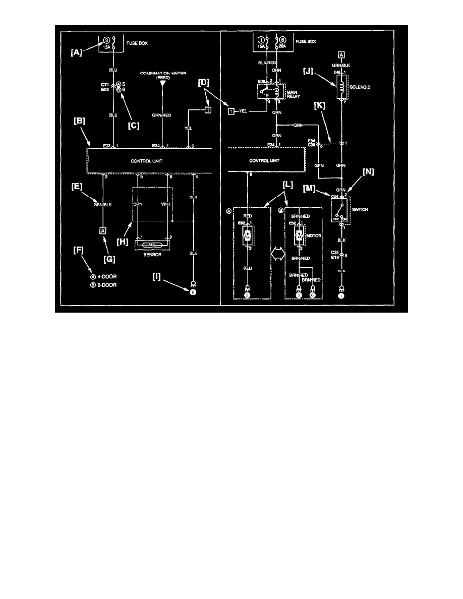
The circuit diagram of each system shows the electric circuit from the main fuse, fuse box or the ignition switch (at the top in the diagram) to the ground
(at the bottom) so that the circuit can be followed easily when performing inspection and service work.
Further information on connector, ground point and fuses is provided by cross-reference of "SYSTEM CIRCUIT DIAGRAM" and the other systems as
described in the preceding indications.
Connector code, ground No. and fuse No. are the reference code for cross-reference.
[A]: Fuse No.
This No. indicates the reference code to power supply diagram. (Refer to ("POWER SUPPLY DIAGRAM") for the continuity of the upper circuit.)
[B]: Connector mark
This indicates that the connector is identical.
[C]:
Variations by specifications are identified by codes.
[D]:
This indicates continuity between the same symbol.
[E]: Wire color
This indicates the wire color. (Refer to "WIRE COLOR SYMBOLS".)
[F]: