
Esteem GLX Wagon Plus L4-1.8L (1999)
This indicates the variations by the specifications.
[G]:
This indicates that the circuit is continued to the same symbol.
[H]:
This indicates that the shield wire.
[I]: Ground point
This indicates the ground No. (Refer to ("GROUND POINT") for the location.)
[J]: Symbol mark
Symbol marks are used for better legibility. For more information, refer to "SYMBOLS AND MARKS".)
[K]: Identical marks
This indicates that the intermediate connector is identical.
[L]:
This indicates variation of circuit depending on specifications.
[M]: Connector code
This indicates the reference code to ("CONNECTOR LAYOUT DIAGRAM") or ("LIST OF CONNECTORS") for further information.
[N]: Pin No.
This indicates the pin No. (Refer to ("LIST OF CONNECTORS") for the pin position in the connector.)
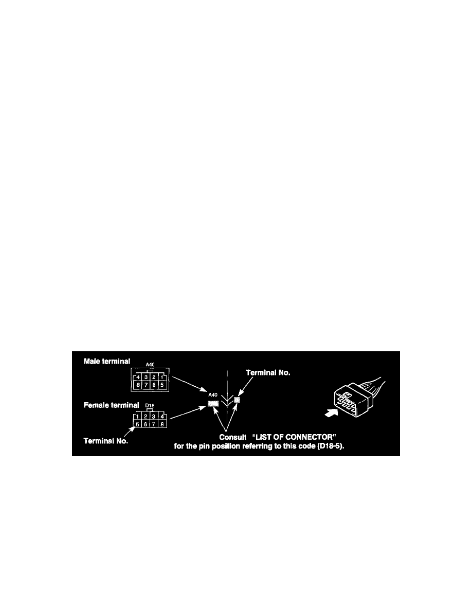
Indication of Connectors and How to Read Them
The connectors are indicated as shown in ("SYSTEM CIRCUIT DIAGRAM"). For the shape and pin arrangement of each connector used, refer to
("LIST OF CONNECTORS"). Described below are how they are indicated and how to read them.
1.
-
The male terminal and female terminal are identified by a double enclosure and a single one respectively.
-
The intermediate connector which connects harnesses is shown by both shapes of the male terminal and the female terminal but the connector
to be connected directly to the equipment is shown by the shape of the connector on the harness side.
-
The connectors described are always "harness side connectors" which are viewed from the direction.