
Esteem GLX Wagon Plus L4-1.8L (1999)
Wheel Speed Sensor: Description and Operation
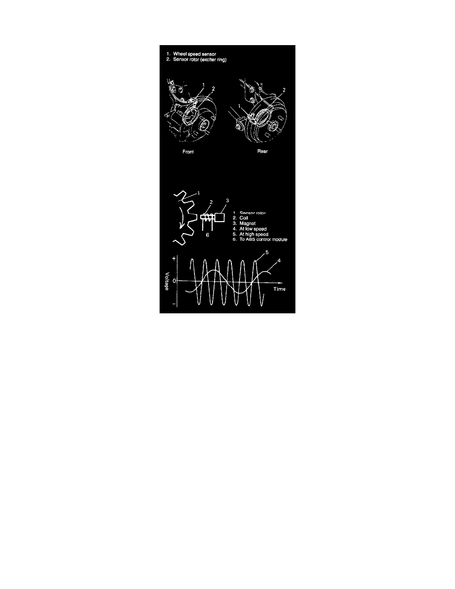
WHEEL SPEED SENSOR AND ROTOR
The wheel speed sensor consisting of a magnet and a coil is installed to each of the knuckles of 4 wheels. The sensor rotor (exciter ring) is installed to
each of the right and left drive shaft at its outside joint as well as to the right and left rear wheel hubs. A specified amount of clearance (air gap) is
provided between the sensor and rotor for their installation.
When the rotor with serration (tooth) turns, the magnetic flux emitted from the magnet of the speed sensor varies and an alternate current voltage
occurs in the coil. As the frequency of this alternate current voltage varies in proportion with the revolution speed of wheels, each wheel speed is
detected from it.
NOTE:
^
Clearance between the sensor and the rotor (ring) cannot be adjusted.
^
Do not remove rotor (ring) from drive shaft joint or rear wheel hub.