
Esteem GLX Wagon Plus L4-1.8L (1999)
positions of pins in the connector when checking continuity between pins, etc. Please note that the list is drawn to symbolize the basic configurations of
the connectors and some connectors in the list may discrepant to the actual ones depending on the specifications.
HOW TO USE LIST OF CONNECTORS:
It is easily possible to find the shape of the connector of interest and its pin positions by locating the same connector code and the pin Nos. as those in
("SYSTEM CIRCUIT DIAGRAM") from ("LIST OF CONNECTORS").
For further information on its use, refer to "INDICATION OF CONNECTORS AND HOW TO READ THEM".
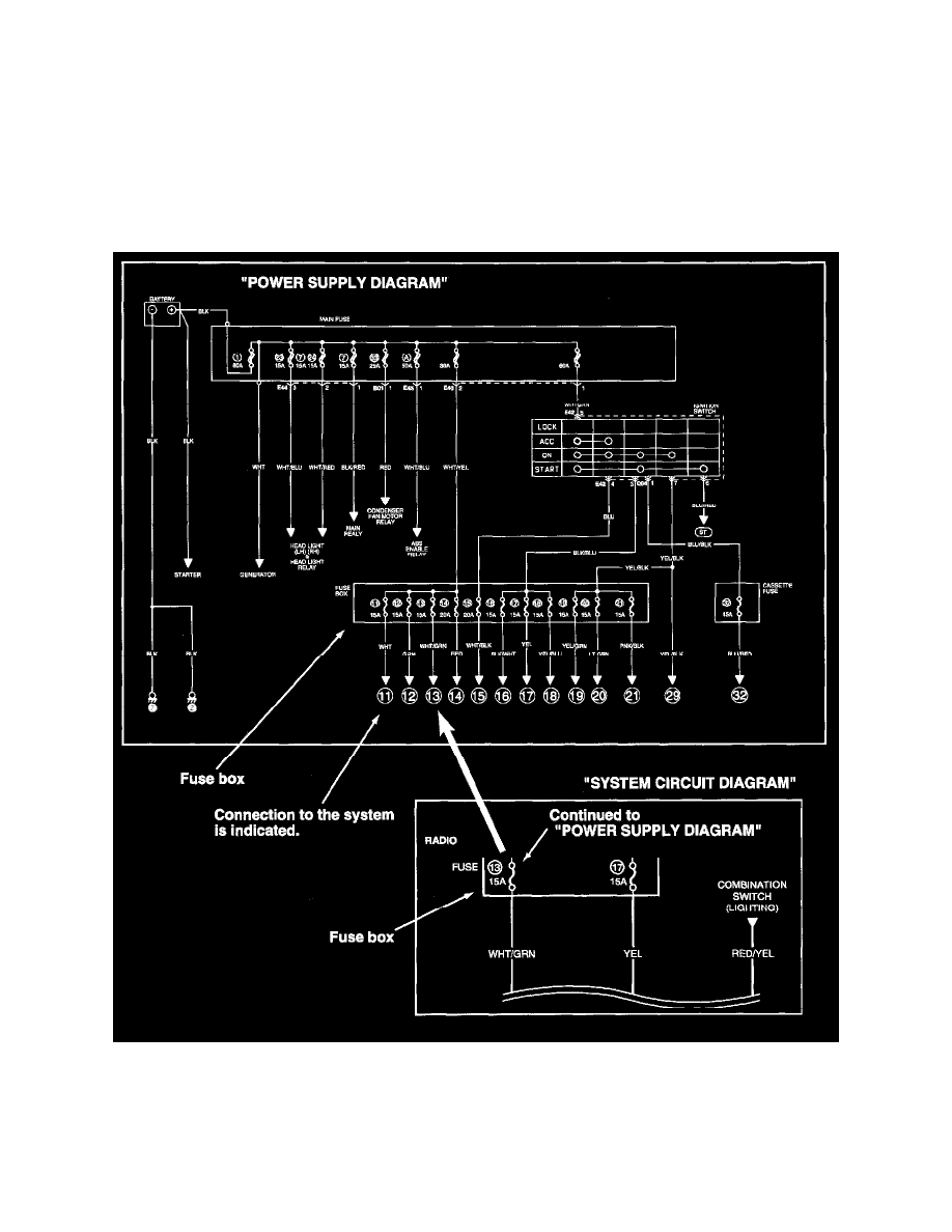
How to Read Power Supply Diagram
Power supply diagram shows the circuit from the positive terminal of the battery to each fuse in the box and where each fuse is connected (each system
circuit name). In addition, the electric load value of each fuse is indicated.
Since every ("SYSTEM CIRCUIT DIAGRAM") is drawn from the circuit down the fuse, cross-refer to ("POWER SUPPLY DIAGRAM") for the
continuity of the upper circuit referring to fuse No. at each fuse symbol mark.
How to Read System Circuit Diagram