
Forenza L4-2.0L (2004)
5. With the compressor mounted to the holding fixture J-34992, position the rotor and bearing assembly on the compressor housing.
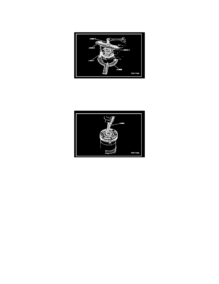
6. Position the pulley rotor and bearing installer J-33017 and the puller pilot J-33023-A directly over the inner race of the bearing.
7. Position the puller crossbar J-8433-1 center forcing bolt on the puller pilot J-33023-A and assemble the two through-bolts and the washers through
the slots on the puller crossbar J-8433-1. Thread the through-bolts into the holding fixture J-34992. The thread of the through-bolts should engage
the full thickness of the fixture.
8. Tighten the center forcing screw J-8433-3 in the puller crossbar J-8433-1 to force the pulley rotor and bearing assembly onto the compressor
housing.
9. Install the rotor and bearing assembly retainer ring using the snap ring pliers J-6083.
10. Reinstall the clutch drive plate and hub assembly.
11. Install the compressor.
12. Connect the negative battery cable.
13. Evacuate and recharge the A/C system. Refer to Discharging, Adding Oil, Evacuating, and Charging Procedures for A/C system.