
Forenza L4-2.0L (2004)
Compressor Clutch Bearing: Service and Repair
Clutch Rotor and Bearing Disassembly and Installation
Tools Required:
J-6083 Snap Ring Pliers
J-9398-A Bearing Remover
J-9481 Bearing Installer
J-33020 Pulley Puller
J-33023-A Puller Pilot
J-33019 Bearing Staking Tool Set
Includes: J-33019-1 Bearing Staking Guide
Includes: J-33019-2 Bearing Staking Pin
J-33017 Pulley Rotor and Bearing Installer
J-8433-1 Puller Crossbar
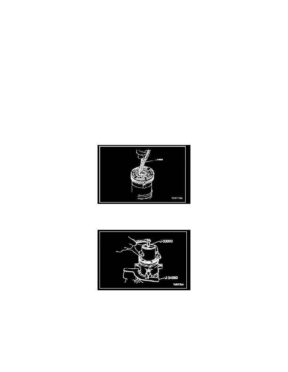
J-34992 Compressor Holding Fixture
J-8092 Driver Handle
J-8433-3 Forcing Screw
Disassembly
1. Disconnect the negative battery cable.
2. Recover the refrigerant. Refer to Discharging, Adding Oil, Evacuating, and Charging Procedures for A/C system.
3. Remove the compressor.
4. Remove the clutch drive plate and hub assembly.
5. Remove the pulley rotor and bearing assembly retaining ring using the snap ring pliers J-6083.
6. With the compressor mounted to the compressor holding fixture J-34992, install the pulley puller J-33020 into the inner circle of slots in the pulley
rotor. Turn the pulley puller J-33020 clockwise in the slots to engage the puller tangs with the segments between the slots in the rotor.
7. Hold the pulley puller J-33020 in place and tighten the puller bolt against the compressor shaft to remove the pulley rotor and bearing assembly.
8. Remove the puller bolt from the pulley puller J-33020. With the puller tangs still engaged in the rotor slots, invert the assembly onto a solid flat
surface or blocks.