
Forenza L4-2.0L (2004)
Data Link Connector: Testing and Inspection
Data Link Connector Diagnosis
Data Link Connector Diagnosis
Circuit Description
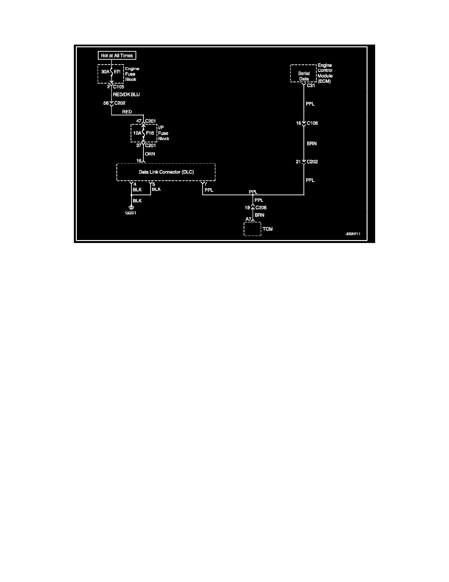
The provision for communicating with the Engine Control Module (ECM) is the Data Link Connector (DLC). It is located under the instrument panel.
The DLC is used to connect the scan tool. Battery power and ground is supplied for the scan tool through the DLC. The Keyword 2000 serial data circuit
to the DLC allows the ECM to communicate with the scan tool. A Universal Asynchronous Receiver Transmitter (UART) serial data line is used to
communicate with the other modules such as the Electronic Brake Control Module (EBCM), the Supplemental Inflatable Restraint (SIR) system. and the
Instrument Panel Cluster.
Diagnostic Aids
Ensure that the correct application (model line, car year, etc.) has been selected on the scan tool. If communication still cannot be established, try the
scan tool on another vehicle to ensure that the scan tool or cables are not the cause of the condition. An intermittent may be caused by a poor connection,
rubbed through wire insulation, or a broken wire inside the insulation. Any circuitry that is suspected of causing an intermittent complaint should be
thoroughly checked for the following conditions:
^
Backed-out terminals
^
Improper mating of terminals
^
Broken locks
^
Improperly formed or damaged terminals
^
Poor terminal-to-wiring connection
^
Physical damage to the wiring harness
^
Corrosion
Test Description
Number(s) below refer to the step number(s) on the Diagnostic Table.
1. The On-Board Diagnostic (OBD II) System Check prompts the technician to complete some basic checks and store the Freeze Frame and failure
records data on the scan tool if applicable. This creates an electronic copy of the data taken when the malfunction occurred. The information is
then stored on the scan tool for later reference.
2. Unlike the UART serial data circuit, the only time a Class II serial data circuit has any voltage on it is when a scan tool asks the ECM for
information and sends the information out.
3. Locate and repair any shorts that may have caused the fuse to open before replacement, if the no voltage condition was due to an open fuse.
4. The scan tool or associated cables could be malfunctioning. Refer to the scan tool's manual for repair information.
Troubleshooting