
Grand Vitara 2WD V6-2.5L (2004)
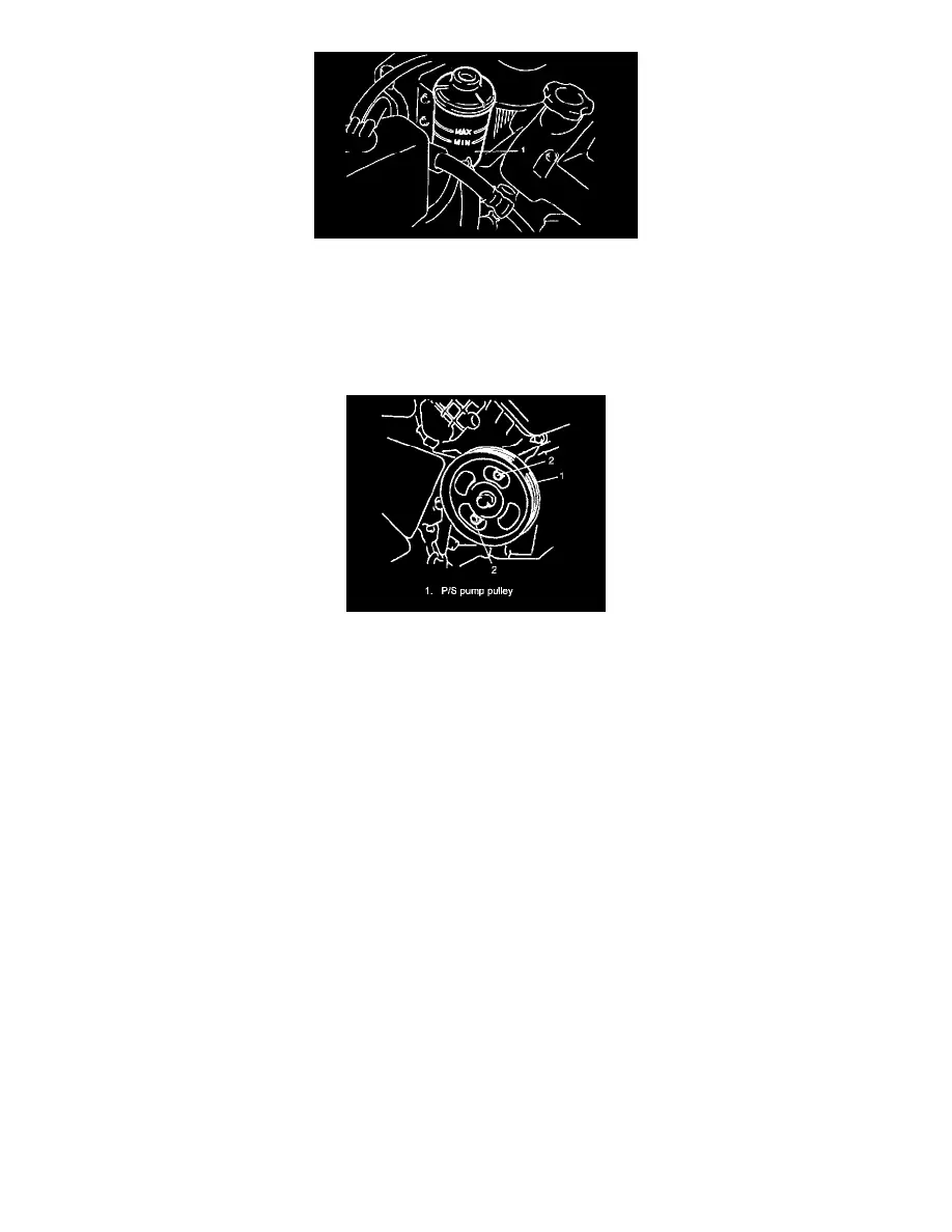
2. Remove P/S fluid reservoir (1) with suction hose.
3. Remove union bolt. Then disconnect high pressure pipe from pump.
NOTE: As fluid flows out of disconnected joints, put a receptacle under joints or a plug to pipe.
4. Disconnect pressure switch lead wire at switch terminal.
5. Loosen related bolts and remove power steering belt.
6. Remove P/S pump mounting bolts (2).
7. Remove P/S pump.
NOTE: Plug each port of removed pump to prevent dust or any other foreign matter from entering.
Installation
Reverse removal procedure, and then noting the following instructions.
NOTE:
^
Using the following specified torques, tighten bolts and nuts ((a), (b), (c), (d), (e), (f), (g), (h), (i), (j) and (k)).
Tightening torque
Pump union bolt (a): 60 Nm (6.0 kg-m, 43.5 ft. lbs.)
Pump bracket bolt (J20 engine model) (b): 25 Nm (2.5 kg-m, 18.5 ft. lbs.)
Pump mounting bolt (G16 and J20 engine models) (c): 25 Nm (2.5 kg-m, 18.5 ft. lbs.)
Pump bracket bolt (G16 engine model) (d): 55 Nm (5.5 kg-m, 40.0 ft. lbs.)
Pipe clamp bolt/reservoir bracket bolt (e): 11 Nm (1.1 kg-m, 8.0 ft. lbs.)
Gear box high pressure pipe union bolt (f): 35 Nm (3.5 kg-m, 25.5 ft. lbs.)
High pressure flare nut (g): 40 Nm (4.0 kg-m, 29.0 ft. lbs.)
Gear box low pressure pipe union bolt (h): 40 Nm (4.0 kg-m, 29.0 ft. lbs.)
Pump bracket bolt (H25 engine model) (i): 45 Nm (4.5 kg, 33.0 ft. lbs.)
Pump mounting bolt (H25 engine model) (j): 45 Nm (4.5 kg-m, 33.0 ft. lbs.)
Tension pulley bolt (H25 engine model) (k): 25 Nm (2.5 kg-m, 18.5 ft. lbs.)
^
Adjust P/S pump drive belt.
^
Fill specified power steering fluid after installation and bleed air without failure.