
Grand Vitara 2WD V6-3.2L (2010)
Hydraulic Control Assembly - Antilock Brakes: Service and Repair
ABS (ESP) Hydraulic Unit / Control Module Assembly
Removal and Installation
Reference: ABS (ESP) Hydraulic Unit / Control Module Assembly On-Vehicle Inspection
CAUTION:
^
Do not give an impact to hydraulic unit.
^
Use care not to allow dust to enter ABS (ESP) hydraulic unit / control module assembly.
^
Do not place ABS (ESP) hydraulic unit / control module assembly on its side or upside down.
Handling it in inappropriate way will affect its original performance.
^
Never disassemble ABS (ESP) hydraulic unit / control module assembly, loosen blind plug or remove motor. Performing any of these
prohibited services will affect original performance of ESP hydraulic unit / control module assembly.
^
Do not allow brake fluid to get on painted surfaces. Painted surfaces will be damaged by brake fluid, flush it with water immediately if
any fluid is spilled.
^
Be sure to tighten fastener to specified torque using torque wrench to avoid damage.
NOTE:
^
For ESP model, be sure to perform Sensor Calibration of ESP Components before performing hydraulic unit operation check when ESP hydraulic
unit / control module is replaced.
^
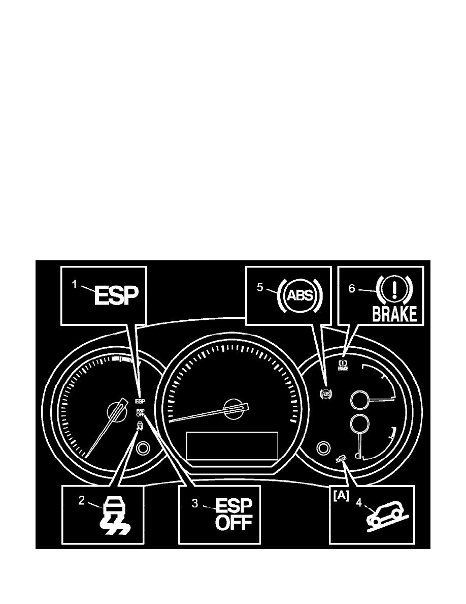
When ignition switch is turned to ON position after replacing ESP hydraulic unit / control module, DTC C1075, C1076, C1078 and C1077 are
stored in ESP control module and the indicator lights light up or flash. However, these are in normal operation. These DTCs are cleared and lights
are turned off if the following operations are performed in order.
1) Sensor Calibration of ESP Components.
2) ABS Hydraulic Unit Operation Check.
3) Ignition switch OFF and ON.