
Grand Vitara 2WD V6-3.2L (2010)
CAN Communication System Circuit Diagram 2
Diagnosis Procedure
NOTE: Before executing items in this flow, be sure to perform CAN Communication System Check. See: Initial Inspection and Diagnostic
Overview/CAN Communication System Check
When "CAN Communication Bus Off" is detected in any control modules, or when it is not possible to communicate with any control modules by using
SUZUKI scan tool (SUZUKI SDT), perform inspection using the following procedure.
1. Connect SUZUKI scan tool (SUZUKI SDT) and have DTC of ECM displayed to check for communication with ECM. If scan tool fails to
communicate with ECM, check SUZUKI scan tool and communication cable, DLC power and ground circuit. If communication is in good
condition, proceed on to next Step.
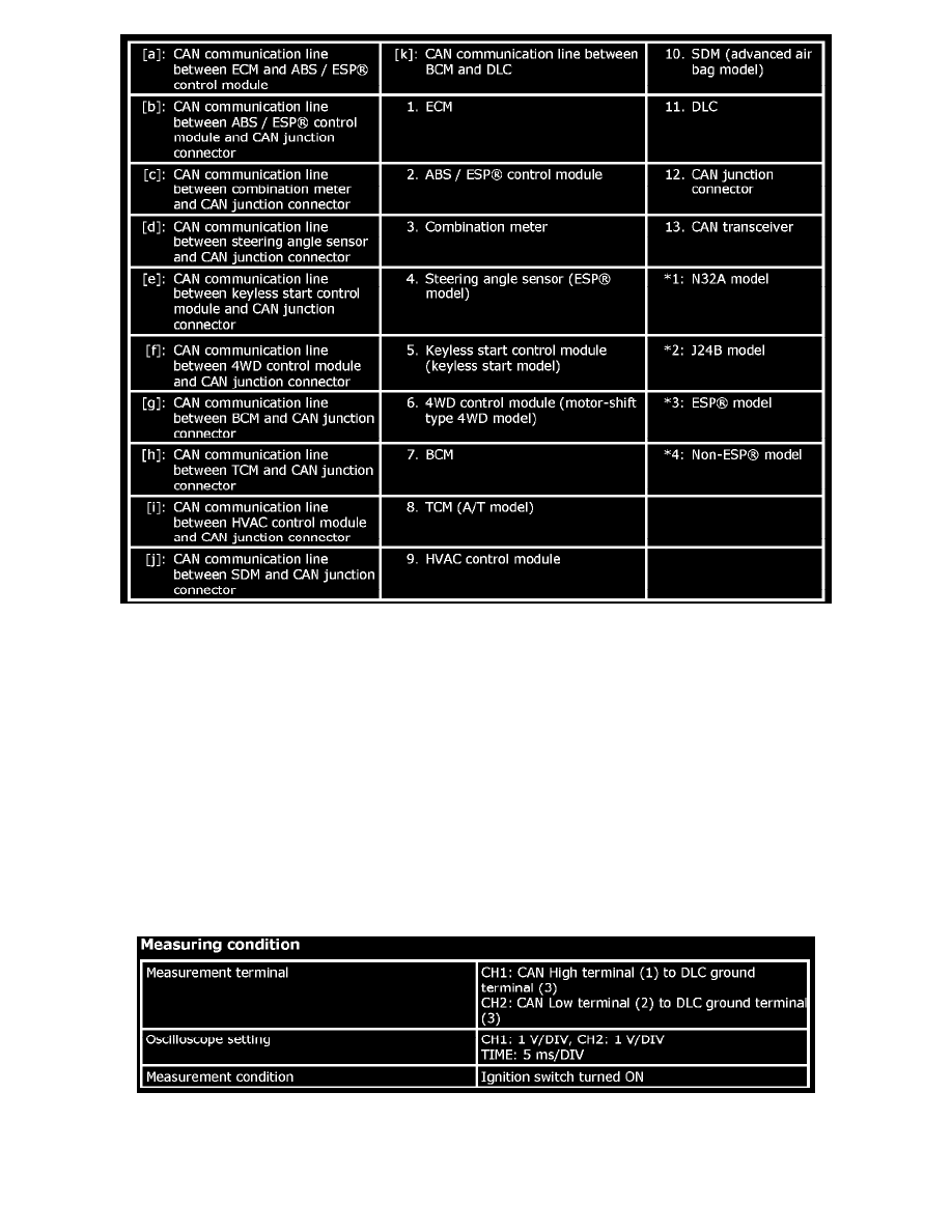
2. Using oscilloscope or oscilloscope function of SUZUKI scan tool (SUZUKI SDT), observe both CAN High terminal (1) and CAN Low terminal
(2) for CAN communication signal waveform at DLC on the following condition when ignition switch is at ON position.
Measuring condition