
Grand Vitara 4WD L4-2.4L (2009)
communicate with ECM, check SUZUKI scan tool and communication cable, DLC power and ground circuit. If communication is in good
condition, proceed on to next Step.
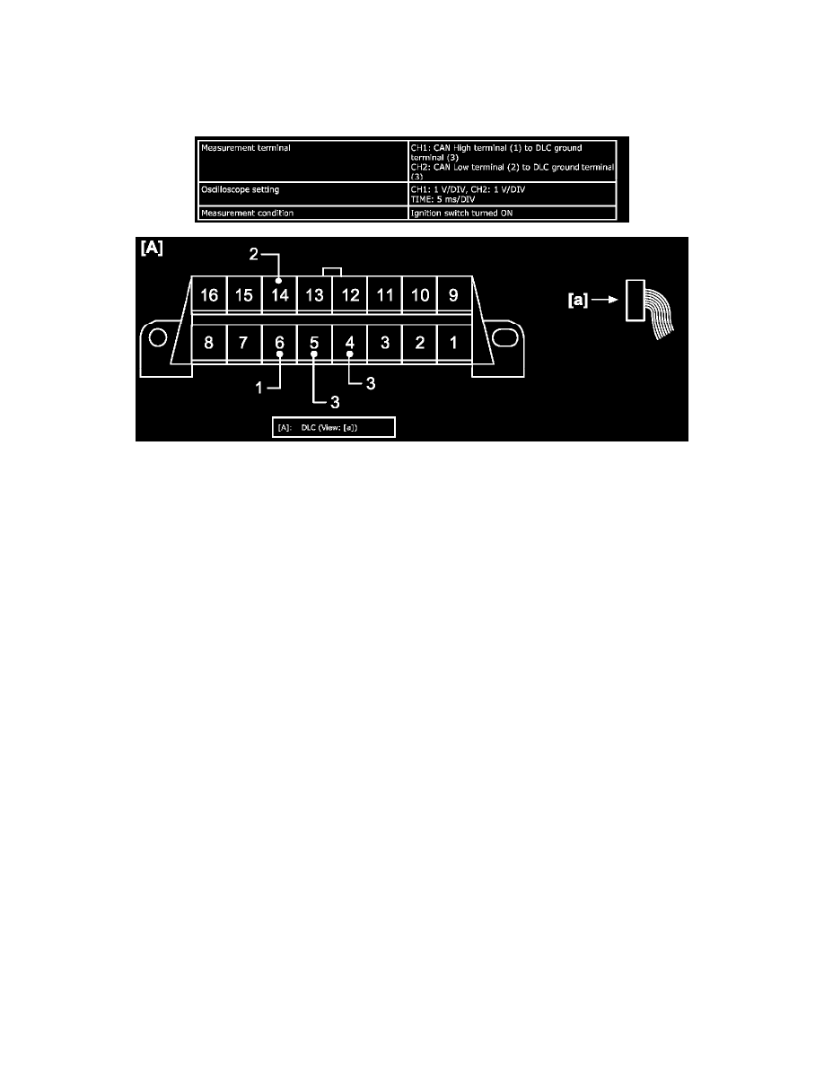
2. Using oscilloscope or oscilloscope function of SUZUKI scan tool (SUZUKI SDT), observe both CAN High terminal (1) and CAN Low terminal
(2) for CAN communication signal waveform at DLC on the following condition when ignition switch is at ON position.
Measuring condition
3. Compare observed signal waveform and waveforms given as Reference Waveform. Find the most similar signal waveform and identify the trouble
system and trouble nature of the applicable "Reference Waveform".
4. Based on identified trouble system and trouble nature, perform troubleshooting according to Troubleshooting (Advanced Air Bag Model) or
Troubleshooting (Non-Advanced Air Bag Model).
Reference Waveform
NOTE:
-
Shown below are waveforms observed with oscilloscope function of SUZUKI scan tool (SUZUKI-SDT) as examples for reference.
-
Waveforms in "Examples of abnormal waveforms" are picked up as samples among CAN communication waveforms during occurrence of
abnormality. However, the same waveform cannot necessarily be observed. Therefore, to identify the content of abnormality, select a waveform
which is the most similar to the observed waveform from Examples of abnormal waveforms.
Normal waveform
Reference voltage is 2.5 V (1) for both CAN High signal (2) and CAN Low signal (3). Waveform of CAN High signal is 2.5 - 3.5 V and that of CAN
Low signal is 2.5 - 1.5 V. For details, refer to "CAN Communication signal" under CAN Communication System Description.