
Grand Vitara 4WD V6-2.5L (2003)
Electronic Brake Control Module: Description and Operation
Type 2
ABS Hydraulic Unit/Control Module Assembly Description
Self-Diagnosis Function
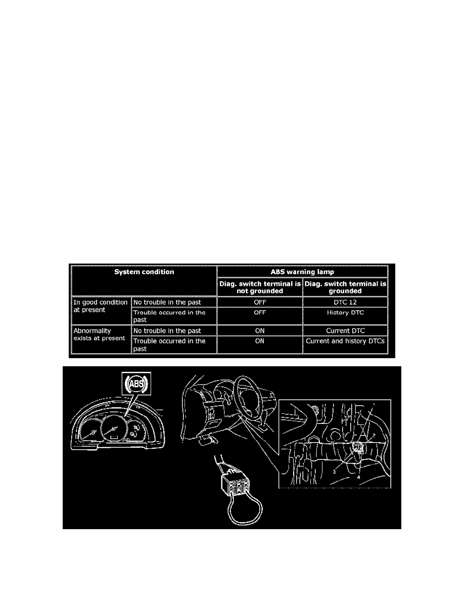
ABS control module diagnoses conditions of the system component parts (whether or not there is any abnormality) all the time and indicates the results
(warning of abnormality occurrence and DTC) through the "ABS" warning lamp as described below.
1) When ignition switch is turned ON, "ABS" warning lamp lights for 2 seconds to check its warning lamp and circuit.
2) When no abnormality has been detected (the system is in good condition), "ABS" warning lamp turns OFF after 2 seconds.
3) When the vehicle starts to move after the ignition switch is turned ON (more than one wheel speed sensor signals are inputted), solenoid valves
and motor of ABS hydraulic unit operate once one after another for electrical check.
During this check, motor operation sound may be heard but that means nothing abnormal.
4) When an abnormality in the system is detected, "ABS" warning lamp lights and the area where that abnormality lies is stored in the memory of
EEPROM in ABS control module.
5) When Diagnosis switch "PNK" wire terminal (2) of cerulean diagnosis connector (monitor connector) (1) is grounded (or connected to "BLK"
wire terminal (3) by service wire (4)), the abnormal area is output as DTC. It is indicated by flashing of "ABS" warning lamp. (Refer to the table
below.)
For procedure to clear all DTC's, refer to DTC Ciearance:Type 2.
6) ABS control module turns ON EBD warning lamp (brake warning lamp) depending on the trouble that detected by the module and EBD warning
lamp does not indicate DTC as well as "ABS" warning lamp
Fail-Safe Function