
Grand Vitara 4WD V6-3.2L (2010)
Information Bus: Description and Operation
CAN Communication System Description
CAN Communication System Description
System Description
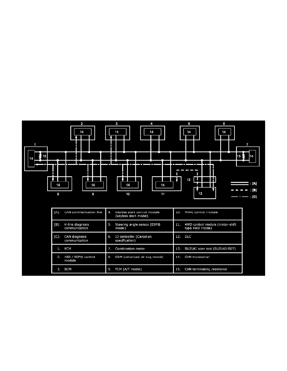
ECM, TCM (A/T model), ABS / ESP(R) control module, BCM, combination meter, 4WD control module (motor-shift type 4WD model), HVAC
control module, keyless start control module (keyless start model), SDM (advanced air bag model), ID controller (Canadian specification) and steering
angle sensor (ESP(R) model) of this vehicle communicate control data between each control module.
Communication of each control module is established by CAN (Controller Area Network) communication system. CAN communication system uses the
serial communication in which data is transmitted at a high speed. It uses a twisted pair of two communication lines (CAN High / CAN Low) for the
high-speed data transmission. As one of its characteristics, multiple control modules can communicate simultaneously. In addition, it has a function to
detect a communication error automatically. Each module reads necessary data from the received data and transmits data.
The system is structured in such way that other control modules / sensors are connected (hooked) to CAN main bus (CAN main circuit) between ECM
and combination meter. ECM and combination meter have a built-in terminating resistance to stabilize the entire CAN bus (CAN circuit). If either
module is disconnected or any abnormality (open or shorted CAN circuit) occurs, CAN bus as a whole becomes unstable and causes malfunction of
CAN communication between modules.
System Block Diagram
Communication with Scan Tool
-
K-line or CAN line is used for communication between each control module and scan tool. Refer to Diagnosis Communication Table to determine
which line is used for communication between each control module and scan tool.
-
ECM, TCM (A/T model), ABS / ESP(R) control module, BCM, SDM (advanced air bag model) and HVAC control module use CAN line for
communication with scan tool. Even if CAN line has a trouble other than between DLC and BCM, communication may also fail between scan tool
and these control modules.
-
4WD control module (motor-shift type 4WD model) use K-line for communication with scan tool. Even if CAN line has a trouble, it is possible to
communicate between scan tool and this control module.
Bus Check Function of SUZUKI Scan Tool (SUZUKI-SDT)
SUZUKI scan tool (SUZUKI-SDT) efficiently diagnoses a CAN bus malfunction by "Communication Bus Check" and "Communication Malfunction
DTC" under "Bus check".
"Communication Bus Check" can display all control modules / sensors name communicated by CAN. (except ID controller)