
Grand Vitara 4WD V6-3.2L (2010)
Circuit Description
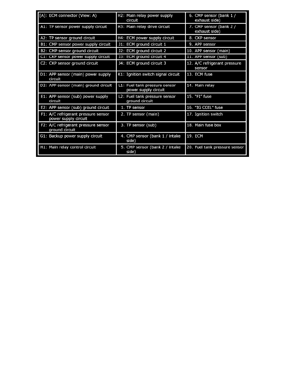
When the ignition switch is turned to ON position, the main relay turns ON (the contact point closes) and the main power is supplied to ECM. And then
ECM supplies 5 V power to each sensor (A/C refrigerant pressure sensor, CKP sensor, CMP sensor, APP sensor and TP sensor).
Troubleshooting
NOTE:
-
Before troubleshooting, perform following items. See: Computers and Control Systems/Testing and Inspection/Initial Inspection and Diagnostic
Overview/Precautions of ECM Circuit Inspection
-
Be sure to read the Precautions of ECM Circuit Inspection:N32A.
-
When measuring circuit voltage and/or pulse signal at ECM connector, connect the special tool to ECM and/or the ECM connectors.
-
Confirm that battery voltage is 12 V or more.
-
Be sure to check related fuses of ECM power circuit for blown out. If fuse is blown out, replace fuse(s) and check circuits connected to blown
fuse(s) for short circuit to ground.
1. Check ECM power supply circuit as follows.
a. Disconnect ECM connectors from ECM with ignition switch turned OFF.
b. Check each terminal of ECM connectors for proper connection.
c. Measure voltage between each terminal of ECM connector and body ground in the following table.
If each measured voltage is out of specified voltage, repair or replace related part.