
Grand Vitara LTD 2WD V6-2.5L (2001)
When using oscilloscope for this check, check if peak-to-peak voltage (1) meets specification and waveform is complete.
Peak-to-peak voltage at 2/3 to one rotation per second (35 - 53 Hz) (Front wheel speed sensor): 150 mV or more
REMOVAL
1. Disconnect negative (-) cable from battery.
2. Hoist vehicle and remove wheel.
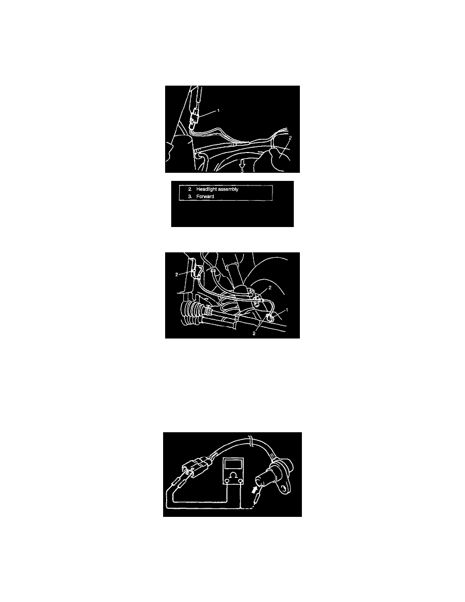
3. Disconnect front wheel speed sensor connector (1).
4. Remove harness clamp bolts (2) and remove front wheel speed sensor (1) from knuckle.
CAUTION:
^
Do not pull wire harness when removing front wheel speed sensor.
^
Do not cause damage to surface of front wheel speed sensor and do not allow dust, etc. to enter its installation hole.
INSPECTION
Sensor
^
Check sensor for damage. If any faulty is found, replace.
^
Check sensor for resistance. If any faulty is found, replace.
Resistance between terminals of wheel speed sensor: 0.8 - 1.6 k Ohms at 20°C (68°F)
Resistance between terminal and wheel speed sensor body: 1 M Ohms or more
Sensor Rotor