
Kizashi AWD L4-2.4L (2010)
Lamp Control Module: Component Tests and General Diagnostics
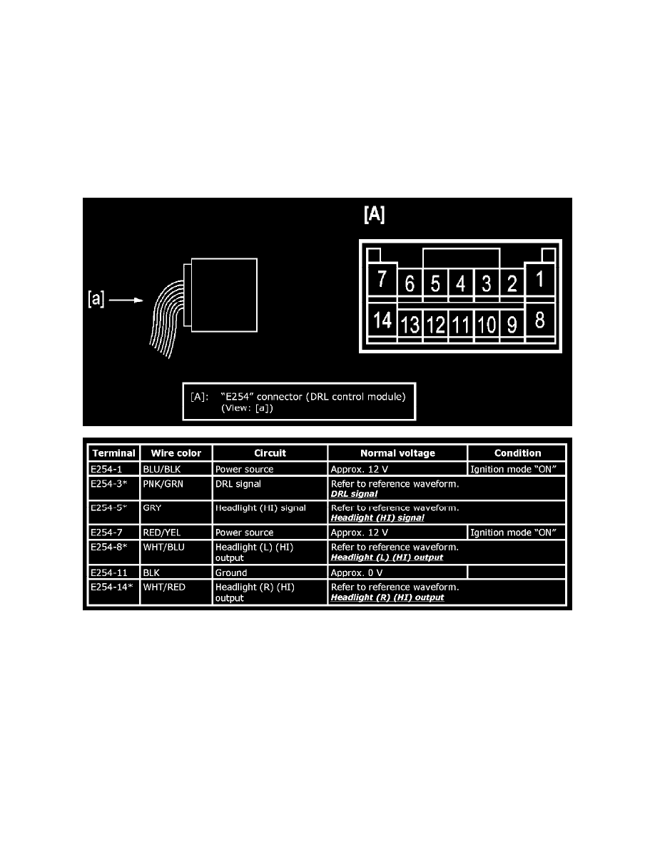
Inspection of DRL Control Module and Its Circuit
Voltage and Signal Check
Check each terminal voltage and output waveform using voltmeter and oscilloscope function of SUZUKI scan tool.
NOTE:
-
Check that battery voltage is 11 V or more.
-
An "ignition mode" in the following table represents a power supply mode available with the keyless push start system. For more details, refer to
Description of Keyless Engine Start Function.
-
Outputs from terminals marked with asterisk (*) cannot be measured with voltmeter because they are pulse signals. Use oscilloscope function of
SUZUKI scan tool for measuring these outputs.
Reference Waveform
Oscilloscope display
Shown below is typical waveform display provided by oscilloscope.
NOTE:
-
Display includes the following types of data: