
Kizashi AWD L4-2.4L (2010)
Information Bus: Initial Inspection and Diagnostic Overview
Precautions For Diagnosing Trouble
Precautions for Diagnosing Trouble
-
Before using SUZUKI scan tool, read its "Operator's (Instructions) Manual" to know how to use it.
-
Diagnosing target control module / sensor only is not enough in order to accurately diagnose any trouble of CAN communication system. Check
communication conditions of overall system (including control modules and sensors related in CAN communication) and diagnose trouble by
putting those information together.
-
It may be possible that CAN system has trouble because of blown fuse or low battery voltage. Before troubleshooting, confirm that fuse, battery
voltage and charging system condition are normal.
-
CAN communication error is detected if connector of control modules or sensor being connected to CAN communication line or applicable fuse is
connected / disconnected while ignition mode is in "ON".
-
Confirm that no equipment or option other than original parts is connected onto CAN bus. If any of those items are connected, disconnect it before
troubleshooting.
-
If any DTCs together with Lost Communication (Reception error) and/or Communication Bus Off are displayed, start troubleshooting of CAN
communication first.
-
Before diagnosing trouble, be sure to check equipment of vehicle being serviced as well as control modules and sensor connected to CAN
communication line.
-
Be sure to clear all DTCs after completing troubleshooting.
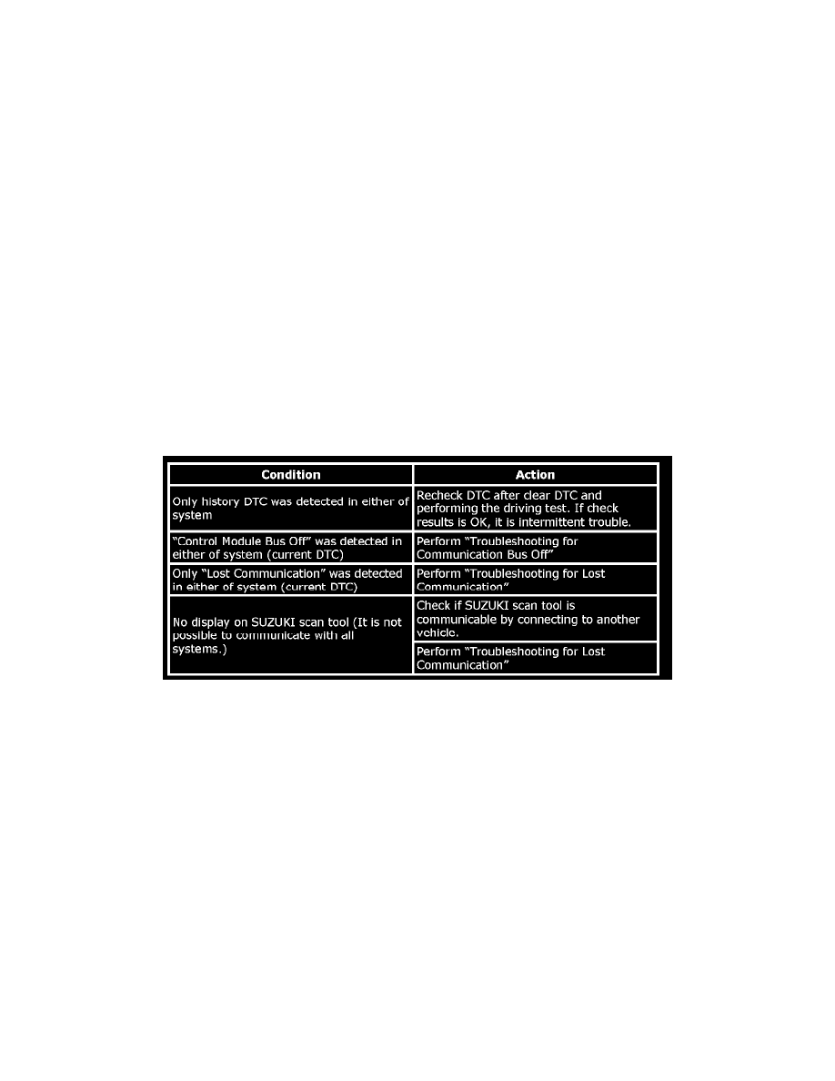
CAN Communication Check
CAN Communication Check
Using SUZUKI scan tool, execute "Communication Malfunction DTC" under "Bus check" and check DTCs of all control modules connected to CAN
Communication Bus.
CAN Communication System Transmitting And Receiving Data Table
CAN Communication System Transmitting and Receiving Data Table
NOTE:
-
T (Transmitting): When two or more control modules start transmission at the same time, control module transmitting the highest priority
information performs transmission right and all other control modules enter reception mode.
-
R (Receiving): All control modules connected with CAN communication lines receive all information on CAN communication line. Each control
module selects only the necessary information for performing its control function.
-
ECM, using wheel speed signal transmitted from ESP(R) control module, calculates and determines vehicle speed and transmits that information
to each control module.