
Kizashi AWD L4-2.4L (2010)
Engine Control Module: Pinout Values and Diagnostic Parameters
Voltage and Signal Check
Inspection of ECM and Its Circuits
Reference: Precautions for Engine
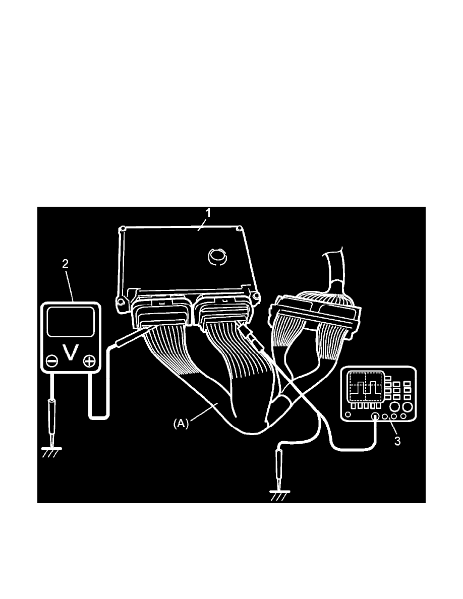
Voltage and Signal Check
1. Remove ECM (1) from its bracket.
2. Connect special tool between ECM and ECM connectors securely.
Special Tool
(A): 09933-06330
3. Check voltage and/or pulse signal using voltmeter (2) and oscilloscope (3).
NOTE:
-
Voltage with asterisk (*) cannot be measured with voltmeter because it is pulse signal. Use oscilloscope for its check if necessary.
-
For "Ignition mode" described in the following table, it means power supply mode in keyless push start system.
For more details of ignition mode, refer to Description of Keyless Engine Start Function