
Reno L4-2.0L (2006)
^
Even though O-rings may look identical, it is extremely important that only recommended service replacement air conditioning O-rings be used or
excessive leakage of refrigerant may occur.
^
Always slip the O-ring onto the flange tube to ensure proper locating and sealing.
Install new SUZUKI-approved service replacement air conditioning (A/C) O-rings whenever a joint or a fitting is disassembled, except when the O-rings
are provided on new components.
When replacing O-rings on an A/C component or a joint connection, the fitting design should be identified to ensure installation of the correct air
conditioning service replacement O-ring. Some joint connections and components will implement a "captured" O-ring design fitting that uses a groove to
retain the O-ring. Others do not have a groove and use a "non-captured" or "standard" O-ring. Assembly and tightening procedures are the same for both
designs, but the O-rings are different.
CAUTION: Before installation, verify that both O-rings and fittings have not been nicked or deformed. Deformed or nicked parts must be replaced.
Failure to use the proper service replacement parts and procedures may result in excessive refrigerant leakage.
Rear Head, Gasket, Valve Plate, Reed Plate, and O-Ring Removal and Installation
Rear Head, Gasket, Valve Plate, Reed Plate, and O-ring Removal and Installation
Tools Required:
J-34993 Cylinder Alignment Rods
Removal
1. Recover the refrigerant. Refer to Discharging, Adding Oil, Evacuating, and Charging Procedures for A/C System.
2. Discharge the A/C system. Refer to Discharging, Adding Oil, Evacuating, and Charging Procedures for A/C System.
3. Remove the compressor.
4. Drain the oil from compressor into a suitable container. Measure and record the amount of oil drained from the compressor. Discard the used oil.
5. Remove the clutch plate and hub assembly.
6. Remove the clutch rotor and bearing.
7. Remove the clutch coil.
8. Remove the compressor through-bolts. Remove and discard the gaskets.
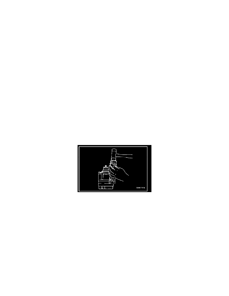
9. Using a wooden block and a plastic-headed hammer, tap around the edge of the rear head to disengage the head from the compressor cylinder.
Separate the rear head, the head gasket, the rear valve plate, the suction reed plate, and the cylinder-to-rear head O-ring. Discard the head gasket
and the O-ring.
Installation
1. Place the rear head on a clean, flat surface. Position the head with the control valve at the 6 o'clock position.
2. Install the cylinder alignment rods J-34993 in the mounting holes at the 11 o'clock and the 5 o'clock positions.
3. Install the head gasket over the cylinder alignment rods J-34993 with the elongated hole at the upper left pin (the 11 o'clock position).
4. Install the rear head valve plate over the guide pins with the elongated hole at the upper left pin. Lower the rear head valve plate into place.
5. Install the suction reed plate over the cylinder alignment rods J-34993. Remove the alignment rod at the 5 o'clock position.
6. Lubricate the cylinder to the new rear head O-ring with clean Polyalkaline Glycol (PAG) refrigerant oil.