
Reno L4-2.0L (2006)
Idle Speed/Throttle Actuator - Electronic: Testing and Inspection
Idle Air Control System Check
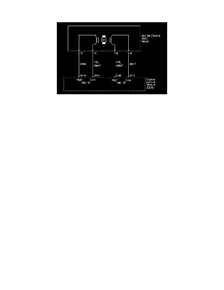
Circuit Diagram
Circuit Description
The Engine Control Module (ECM) controls the engine idle speed with the Idle Air Control (IAC) valve. To increase the idle speed, the ECM pulls the
IAC pintle away from its seat, allowing more air to pass by the throttle body. To decrease the idle speed, it extends the IAC valve pintle toward its seat,
reducing bypass air flow. A scan tool will read the ECM commands to the IAC valve in counts. The higher counts indicate more air bypass (higher idle).
The lower counts indicate less air is allowed to bypass (lower idle).
Diagnostic Aids
If the idle is too high, stop the engine. Fully extend the Idle Air Control (IAC) valve with a IAC driver. Start the engine. If the idle speed is above 800
rpm, locate and repair the vacuum leak. Also, check for a binding throttle plate or throttle linkage or an incorrect base idle setting.
Test Description
The number(s) below refer to step(s) on the diagnostic table.
2. The IAC valve is extended and retracted by the IAC driver. IAC valve movement is verified by an engine speed change. If no change in engine
speed occurs, the valve can be removed from the throttle body and tested. Connect the IAC driver to the removed IAC valve and turn the ignition
ON. Do not start the engine.
5. This step checks the quality of the IAC valve movement in Step
2. Fully extending the IAC valve may cause an engine stall. This may be normal.
6. Steps 2 and 5 verify proper IAC valve operation. This step checks the IAC circuit for a wiring or ECM fault.