
Samurai 2WD L4-1324cc 1.3L SOHC 5 Carb 8V (1987)
Deceleration Valve: Testing and Inspection
Deceleration Mixture Control System
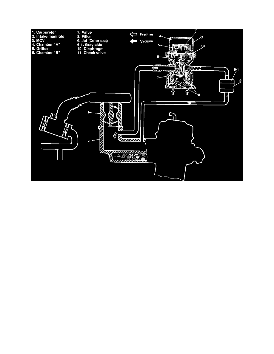
Fig. 17 Deceleration mixture control system schematic
This system, Fig. 17, is designed to allow fresh air into the intake manifold to reduce excessive HC and CO emission caused by temporary rich air fuel
ratio during rapid deceleration.
This system consists of a MCV, jet and vacuum hoses. The MCV consists of a pressure balancing orifice and a check valve on its diaphragm, and
closes when manifold vacuum is constant.
When manifold vacuum becomes constant, pressure difference between chambers A and B, Fig. 17, gradually diminishes through the pressure
balancing orifice, then the MCV.