
Samurai 4WD L4-1324cc 1.3L SOHC 5 Carb 8V (1986)
Thermostatic Air Cleaner Vacuum Switch: Testing and Inspection
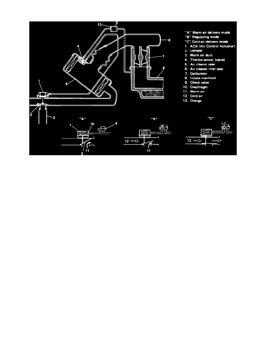
Fig. 20 TCAC system schematic
This system, consisting of an Air Control Actuator (ACA) and a thermo sensor (Thermo Valve), Fig. 20, controls the temperature of the intake air by
mixing preheated air and cool air to improve fuel vaporization and engine warm-up operation. The thermo sensor senses the inside temperature of the air
cleaner and regulates the vacuum applied to the air control actuator, thus controlling the damper position, Fig. 20.
TESTING
THERMOSTATICALLY CONTROLLED AIR CLEANER (TCAC) SYSTEM
1.
Check vacuum hoses for proper installation, deterioration, or damage. Replace as necessary.
2.
With air cleaner cool, disconnect warm air hose from warm air duct.
3.
Reach into warm air duct to check that damper is closed with engine off.
4.
Start engine and run at idle. Damper should open warm air duct.
AIR CONTROL ACTUATOR
1.
Disconnect vacuum hose from ACA.
2.
Using suitable vacuum pump, apply 7.87 inches Hg (20 cm Hg) of vacuum to ACA.
3.
Damper should open fully and remain open with vacuum applied.