
Sidekick 2WD L4-1590cc 1.6L SOHC 0 TBI 8V (1992)
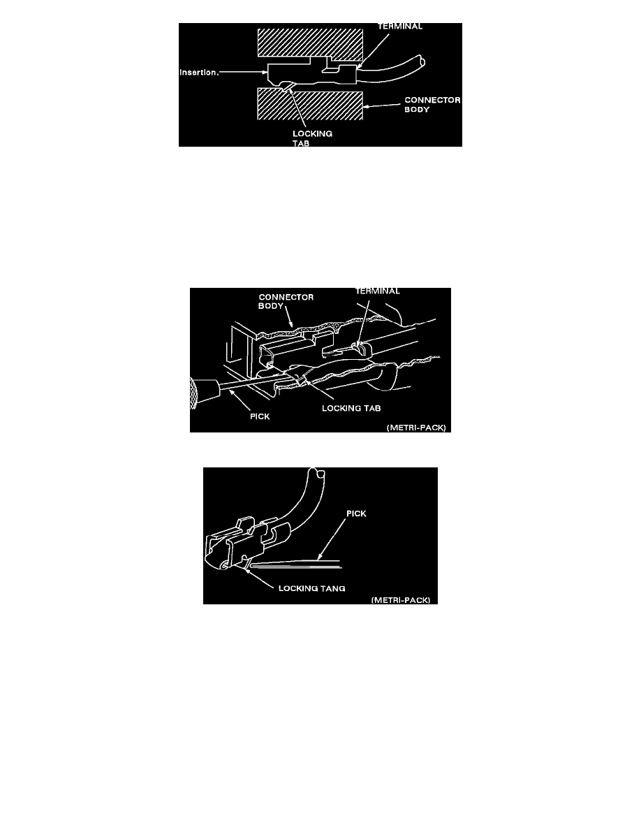
Figure 20 - Typical Pull-To-Seat Connector
Follow the steps below to repair Pull-To-Seat connectors (Figure 20). The steps are illustrated with typical connectors. Your connector may be different,
but the repair steps are similar. Some connectors DO NOT require all the steps shown. Skip the steps that DO NOT apply.
1.
Separate connector halves. Using the proper pick or removal tool, remove terminal (see Figures 21 & 22).
a.
Pull lead gently.
b.
Insert pick from front of connector into canal.
c.
Pry tab up with tool.
d.
Push lead to remove.
Figure 21
Figure 22
2.
If terminal is to be re-used, re-form locking tang.
3.
Make repair.
a.
Pull terminal wire out of connector body.
b.
Cut wire as close to terminal as possible.
c.
Strip 5 mm (3/16") of insulation from the wire (see Figure 23).
d.
Crimp new terminal to wire.
e.
Solder with rosin core solder.
f.
Carefully pull on wire to draw terminal into connector body until it locks.
Basic Troubleshooting Guide
TROUBLESHOOTING GUIDELINES
Without a basic knowledge of electricity, it will be difficult to use the diagnostic procedures contained in this section. You should understand the
basic theory of electricity and know the meaning of voltage, current (amps) and resistance (ohms). You should understand what happens in a