
Sidekick 4WD L4-1590cc 1.6L SOHC 0 TBI 8V (1990)
CAUTION: Fusible links cut longer than 225 mm (approx 9 in.) will not provide sufficient overload protection.
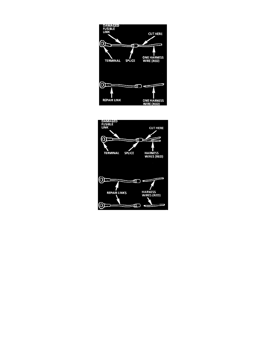
Fig. 4 Single Wire Feed Fusible Link
Fig. 5 Double Wire Feed Fusible Link
To replace a damaged fusible link, Fig. 4, cut it off beyond the splice. Replace with a repair link. When connecting the repair link, strip wire and
use staking-type pliers to crimp the splice securely in two places. For more details on splicing procedures, see Diagnostic Aids/Connector and
Wire Repair. Use Crimp and Seal splices whenever possible.
To replace a damaged fusible link which feeds two harness wires, cut them both off beyond the splice. Use two repair links, one spliced to each
harness wire, Fig. 5.
Repairing Connectors
The following general repair procedures can be used to repair most types of connectors. The repair procedures are divided into three general groups:
Push-to-Seat and Pull-to-Seat and Weather Pack.
^
See CONNECTOR TERMINAL I.D. to determine which type of connector is to be serviced.
^
Use the proper Pick(s) or Tool(s) that apply to the terminal.
^
The GM Terminal Repair Kit (J 38125-A) contains further information.
PUSH-TO-SEAT AND PULL-TO-SEAT