
Sidekick 4WD L4-1590cc 1.6L SOHC 0 TBI 8V (1990)
Valve Clearance: Adjustments
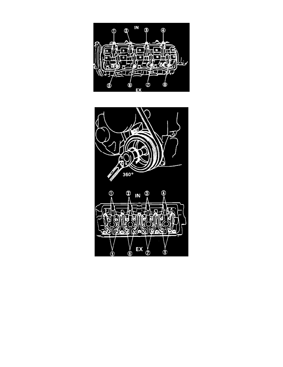
Fig. 14 Valve Identification. 8 Valve Engines
Fig. 15 Valve Identification. 16 Valve Engines
1.
Disconnect battery ground cable, then remove cylinder head cover.
2.
Rotate crankshaft clockwise using a 17 mm socket until ``V'' mark on pulley aligns with ``0'' calibration on timing belt cover.
3.
Remove distributor cap and check rotor position. If rotor is pointing to No. 1 cylinder on distributor cap, check valve lash at valves 1, 2, 5 and 7,
Figs. 14 and 15. If rotor is pointing to No. 4 cylinder on distributor cap, check valve lash at valves 3, 4, 6 and 8, Figs. 14 and 15.
4.
If valve lash is out of specification, adjust as necessary. Use tappet adjuster wrench 09917-18210 or equivalent for 16 valve models.
5.
Install cylinder head cover, then connect battery ground cable.
Valve Adjustment Specifications:
1989-1991
Intake (Cold) ..................................................................................................................................................... 0.13 - 0.17 mm (0.0051 - 0.0067 in.)
Exhaust (Cold) .................................................................................................................................................. 0.15 - 0.19 mm (0.0063 - 0.0075 in.)
Intake (Hot) ....................................................................................................................................................... 0.23 - 0.27 mm (0.0091 - 0.0106 in.)
Exhaust (Hot) .................................................................................................................................................... 0.25 - 0.29 mm (0.0102 - 0.0108 in.)