
Sidekick 4WD L4-1590cc 1.6L SOHC 0 TBI 8V (1990)
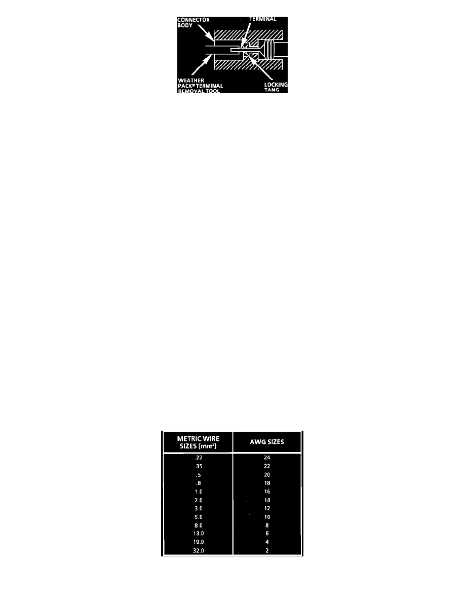
Fig. 21 Typical Weather Pack Connector and Terminal
Follow the steps below to repair Weather Pack(R) connectors, Fig. 21.
Step 1:
Separate the connector halves.
Step 2:
Open secondary lock. A secondary lock aids in terminal retention and is usually molded to the connector.
Step 3:
Grasp the lead and push the terminal to the forward most position. Hold the lead at this position.
Step 4:
Insert the Weather Pack(R) terminal removal tool into the front (mating end) of the connector cavity until it rests on the cavity shoulder.
Step 5:
Gently pull on the lead to remove the terminal through the back of the connector.
NOTICE: Never use force to remove a terminal from a connector.
Step 6:
Inspect the terminal and connector for damage. Repair as necessary, see TERMINAL REPAIR.
Step 7:
Reform the lock tang and reseat terminal in connector body.
Step 8:
Close secondary locks and join connector halves.
Splicing Copper Wire Using Crimp and Seal Splice Sleeves
DESCRIPTION
Crimp and Seal splice sleeves may be used on all types of insulation except tefzel and coaxial to form a one to one splice. They are to be used
where there are special requirements such as moisture scaling. (Crimp and Seal splice sleeves are included in the GM J 38125-A Terminal Repair
Kit.)
Step 1: Open the Harness
If the harness is taped, remove the tape. To avoid wire insulation damage, use a sewing "seam ripper" to cut open the harness (available from
sewing supply stores). The Crimp and Seal splice sleeves may be used on all types of insulation except tefzel and coaxial and may only be used to
form a one to one splice.
Step 2: Cut the Wire
Begin by cutting as little wire off the harness as possible. You may need the extra length of wire later if you decide to cut more wire to change the
location of a splice. You may have to adjust splice locations to make certain that each splice is at least 40 mm (1.5 in.) away from other splices,
harness branches or connectors. This will help prevent moisture from bridging adjacent splices and causing damage.
Fig. 6 Wire Size Conversion Table