
Sidekick JS 2D 2WD L4-1.6L (1998)
Throttle Position Sensor: Adjustments
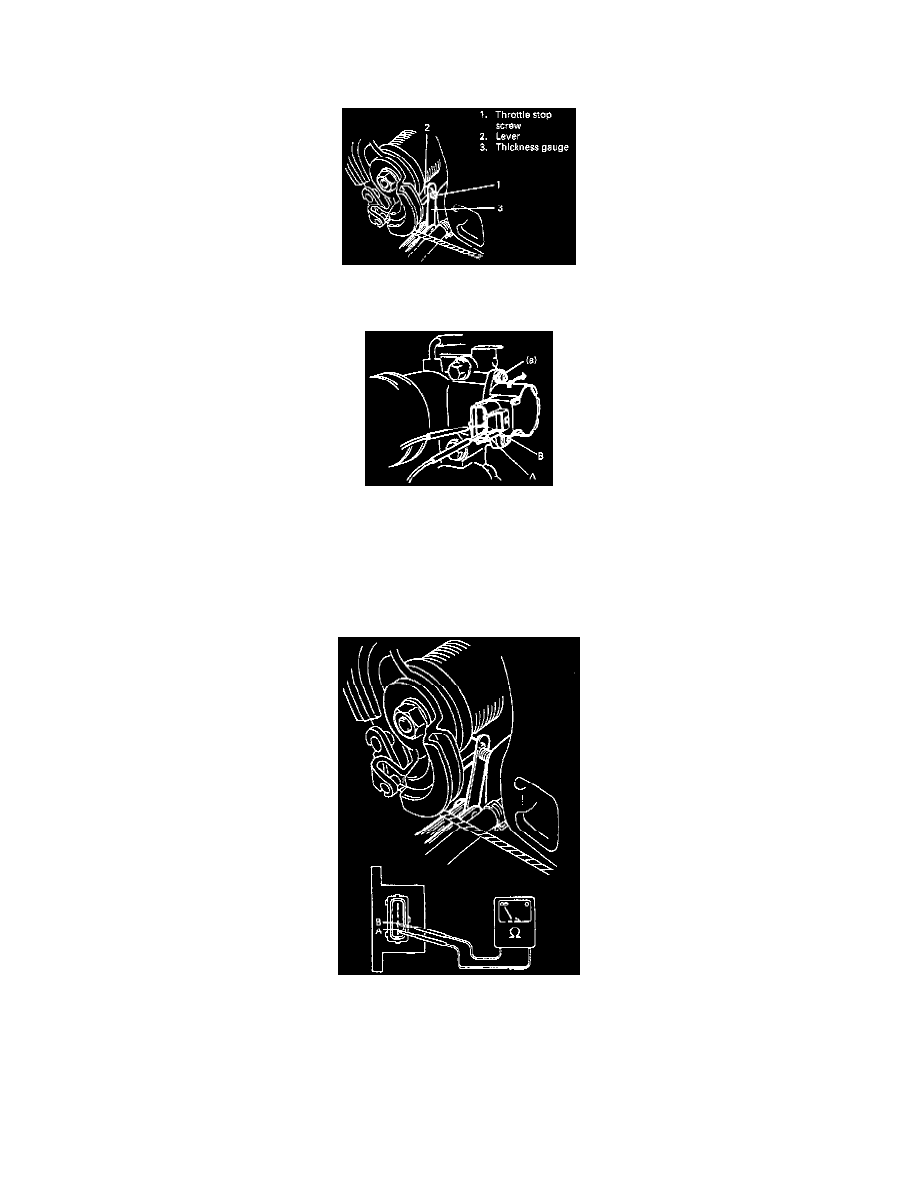
Adjustment
1) Disconnect negative cable at battery and disconnect TP sensor coupler.
2) Insert 0.65 mm (0.026 in) thickness gauge between throttle stop screw and throttle lever.
3) Loosen TP sensor screws.
4) Connect ohmmeter between A and B terminals.
5) First, turn TP sensor counterclockwise fully and then clockwise gradually to find position where ohmmeter reading changes from continuity to
(no continuity).
Then fix TP sensor at that position by tightening screw to specified torque.
Tightening Torque
(a): 3.5 N m (0.35 kg-m, 2.5 lb-ft)
6) Check that there is no continuity between terminals A and B when 0.8 mm (0.037 in) thickness gauge is inserted.
7) Check that there is continuity between terminals A and B when 0.5 mm (0.020 in) thickness gauge is inserted. If check result is unsatisfactory
in steps 6) and 7), it means that installation angle of TP sensor is not adjusted properly. Therefore, start all over again from step 1).
CAUTION: As throttle stop screw is factory adjusted precisely, don't remove or adjust it.
8) Connect coupler to TP sensor securely, and connect battery negative cable.