
Sidekick JS 2D 2WD L4-1.6L (1998)
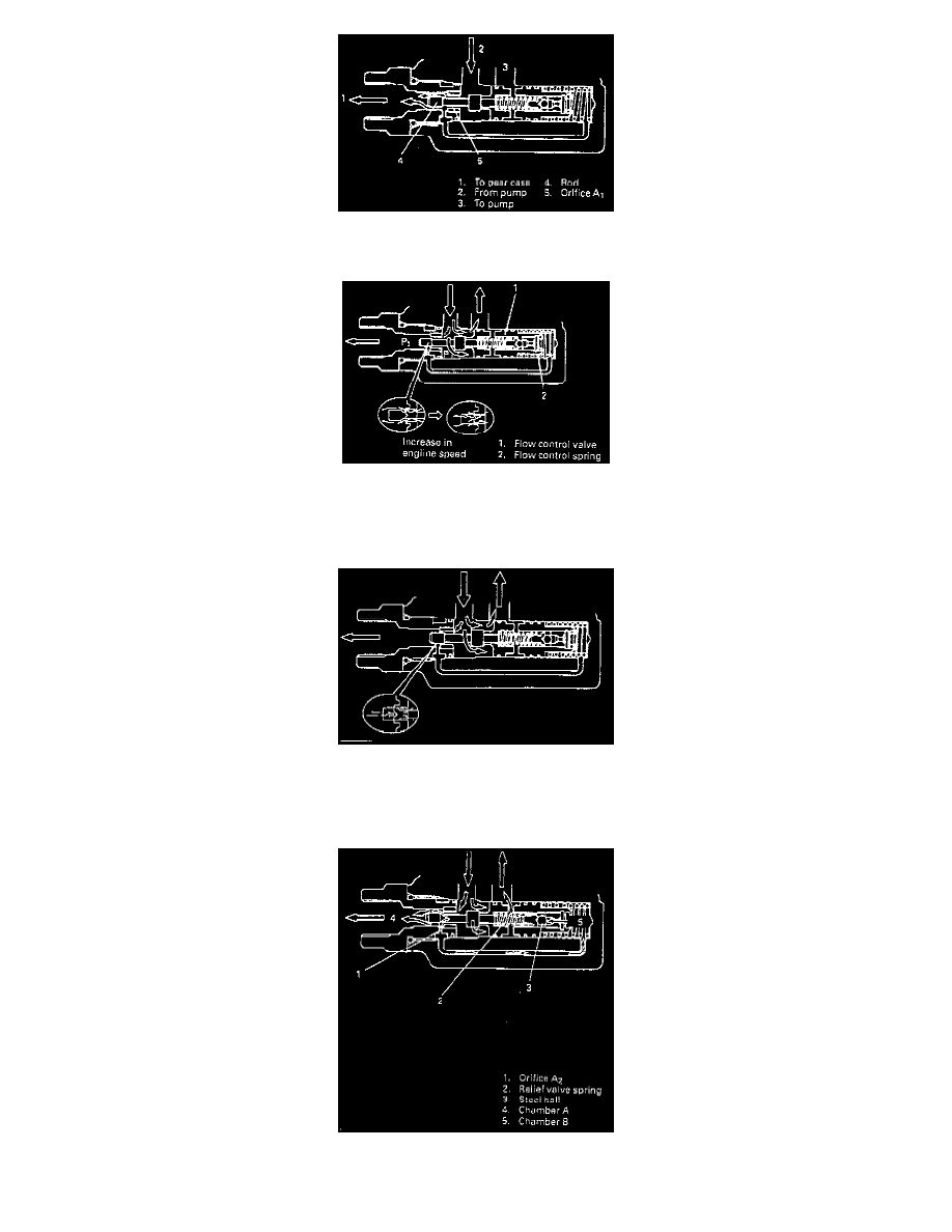
When Idling
The fluid discharged from the pump is supplied through the clearance around the rod in orifice A1, to the gear box.
When Running at Low Speed
As the engine speed rises, the pump discharge rate increases and causes a pressure difference to occur between both ends of the orifice (P1 -
P2). Thus the pressure exceeding the flow control spring force pushes the flow control valve to the right in figure, making the opening in the
orifice narrower through which only a necessary amount of fluid is fed to the gear box and the excess fluid is returned to the pump.
When Running at High Speed
As the engine speed rises higher, opening in the orifice is made narrower and fluid flow to the gear box reduces. As a result, hydraulic pressure
application is slow at the start of the steering wheel turn. This provides straight-ahead stability to suit the driving condition with the steering
wheel operated near its neutral position.
RELIEF VALVE
The relief valve located in the flow control valve controls the maximum hydraulic pressure.