
Sidekick JS 2D 2WD L4-1.6L (1998)
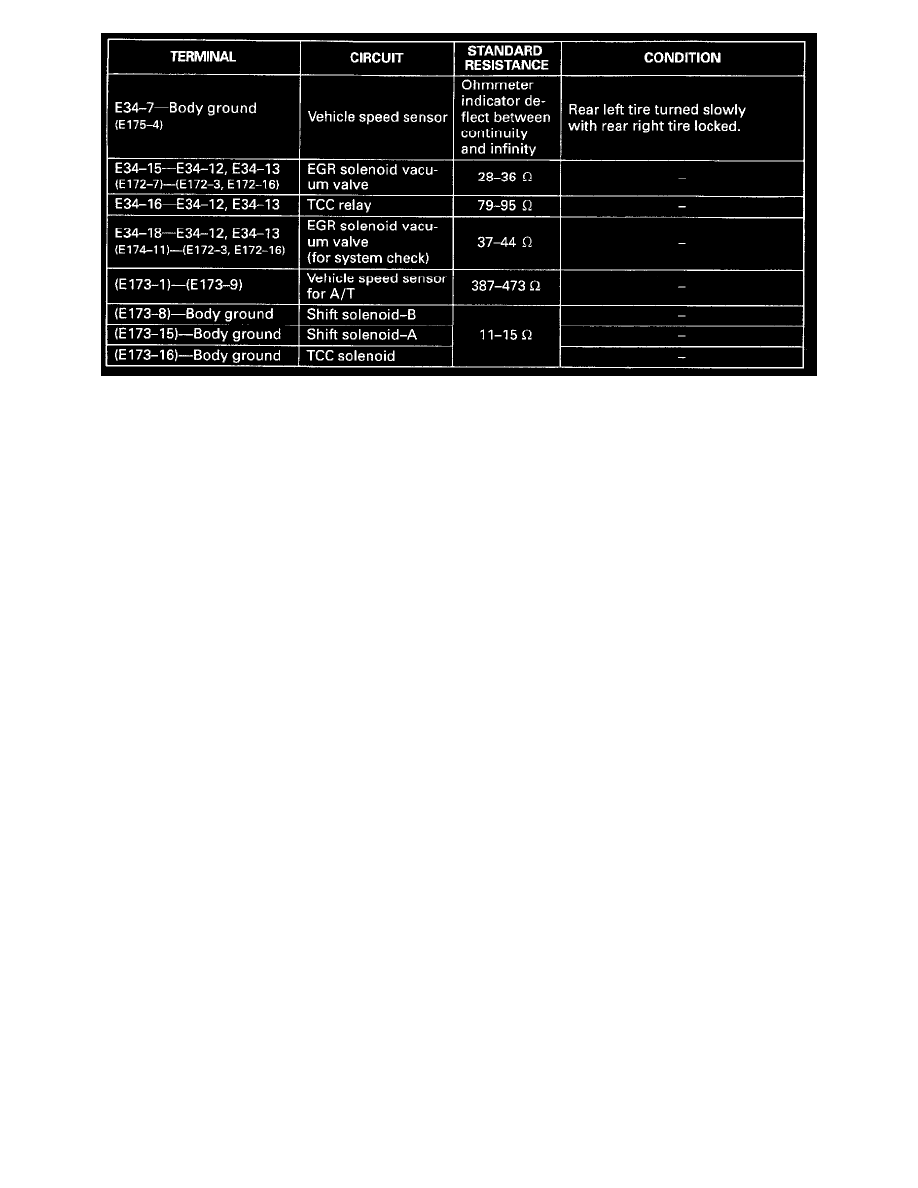
2) Check resistance between each pair of terminals of disconnected couplers as listed in the above table.
CAUTION:
-
Be sure to connect ohmmeter probe from wire harness side of coupler.
-
Be sure to turn OFF ignition switch for this check.
-
Resistance in table represents that when parts temperature is 20°C (68°F).