
Sidekick JS 2D Soft Top 2WD L4-1.6L (1997)
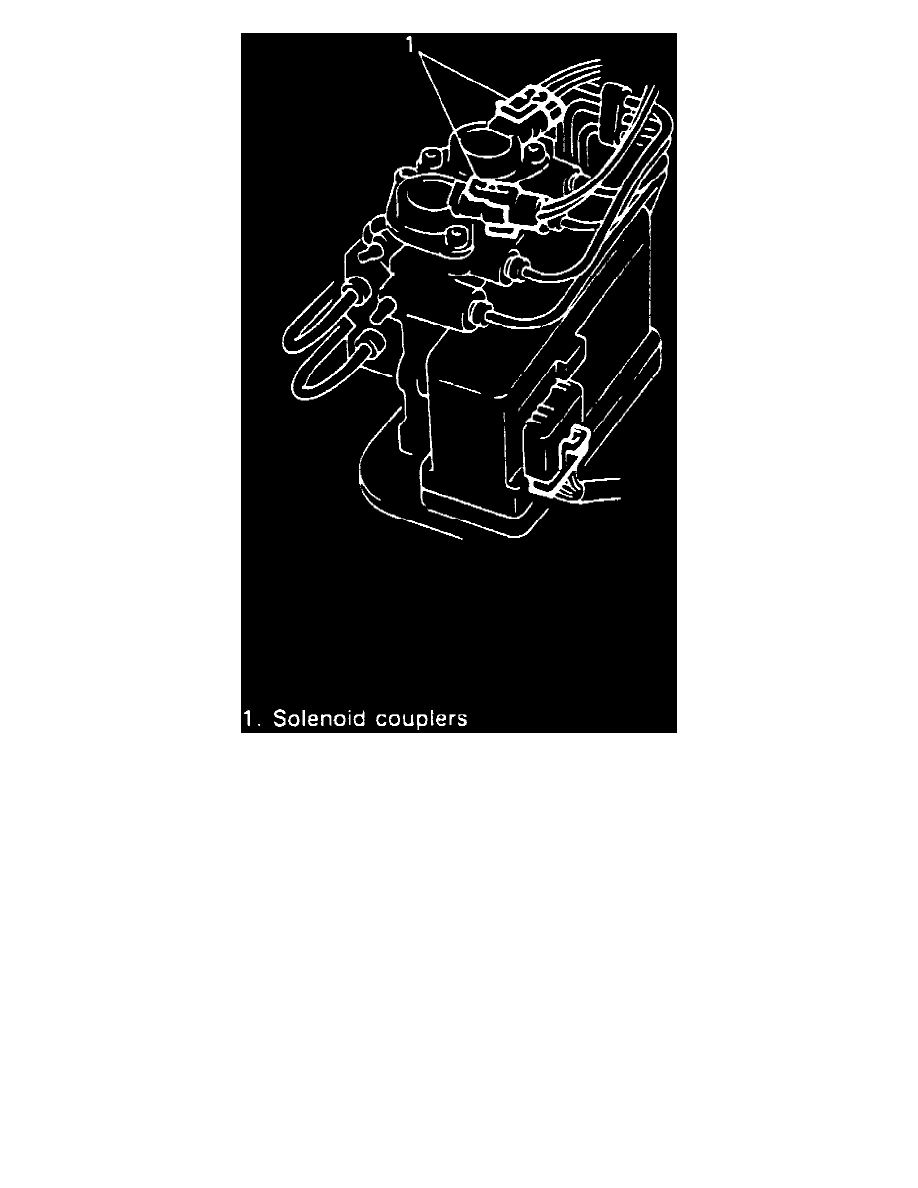
Fig. 15 ABS Solenoid Electrical Connector Location
1. Disconnect battery ground cable, then the two solenoid electrical connectors, Fig. 15.
2. Disconnect fluid level sensor connector, then the 6-pin and 3-pin motor pack electrical connectors.
3. Drain brake fluid from master cylinder
4. Place a shop cloth between brake pipe connections and the top of the motor pack assembly, then disconnect brake pipes from the assembly. Plug
open lines to prevent fluid loss and contamination.
5. Remove two ABS hydraulic modulator assembly attaching nuts.
6. Remove modulator assembly from vehicle.
7. To separate hydraulic modulator from master cylinder, proceed as follows:
a. Remove six Torx head screws that attach gear the gear cover.
b. Remove four Torx head screws that attach the motor pack assembly.
c. Remove two modulator assembly to master cylinder through bolts, then separate master cylinder from modulator assembly.
d. Remove two transfer tubes with O-rings from master cylinder or modulator assembly.
e. Remove through bolt O-rings from master cylinder and modulator assemblies.
f.
If modulator assembly is to be replaced, ensure gears are installed in the same position as they were removed. Refer to ABS Hydraulic
Modulator Gears.
8. Reverse procedure to assemble and install, noting the following:
a. If master cylinder and hydraulic modulator were separated, use new transfer tube assemblies and new O-rings.
b. Torque modulator assembly to master cylinder through bolts to 12 ft. lbs.
c. Torque modulator assembly to vacuum booster nuts to 20 ft. lbs.
d. Bleed hydraulic system as outlined in Brake System Bleed - ABS. See: Brake Bleeding/Service and Repair