
Sidekick JS 2D Soft Top 2WD L4-1.6L (1997)
Removal and Installation
REMOVAL
WARNING: To help avoid personal injury, due to a retained load on the hydraulic modulator/motor pack assembly, the gear tension relief
function of the TECH-1 must be performed prior to removal of the hydraulic modulator.
1) Using the TECH-1, perform the gear tension relief sequence.
2) Disconnect battery negative cable from battery.
3) Drain brake fluid in reservoir, master cylinder and Antilock Brake System (ABS) actuator assembly.
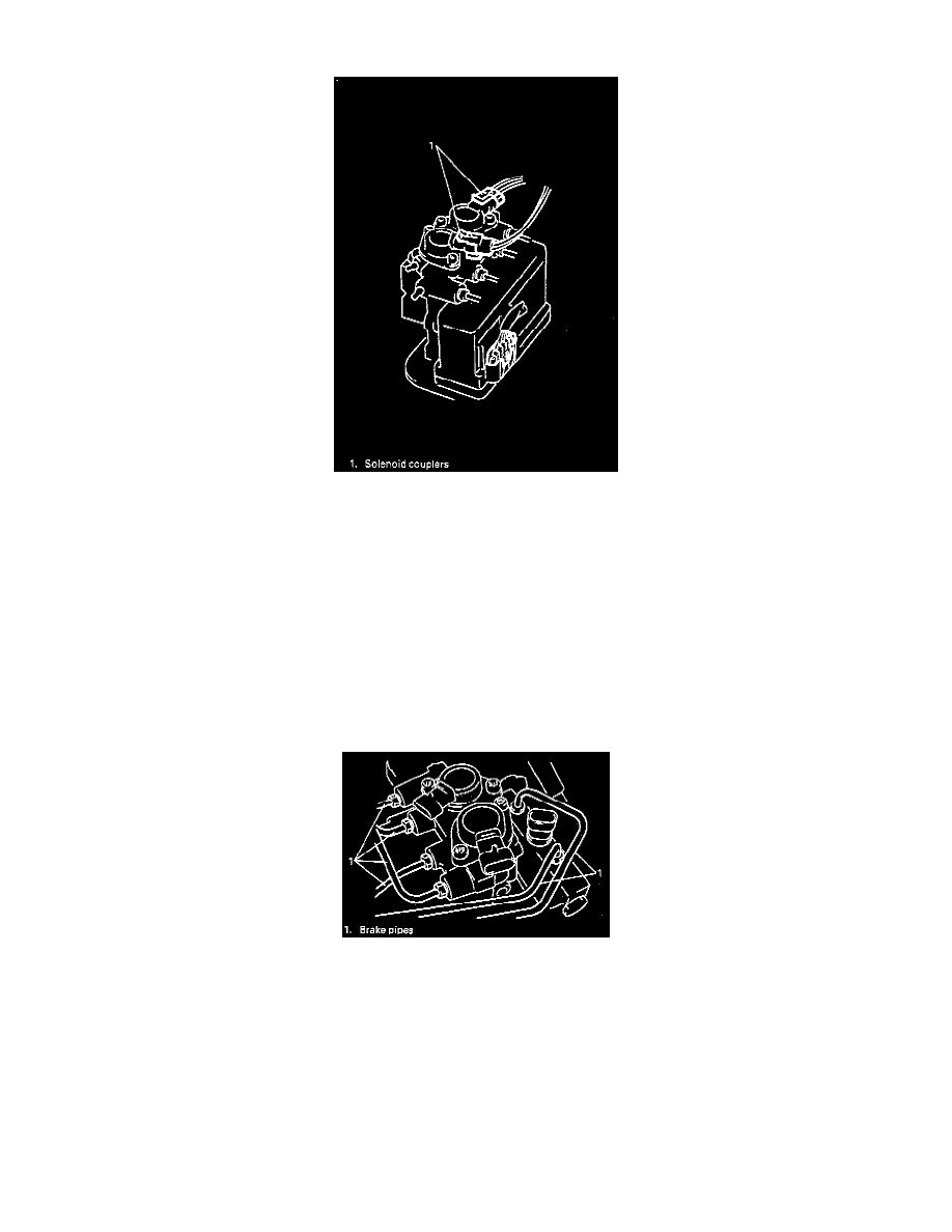
4) Disconnect solenoid, differential switch and motor pack connectors.
NOTE: Place a shop towel beneath the hydraulic modulator brake pipes to prevent brake fluid from contaminating motor pack or electrical
connectors.
5) Remove clamps from brake pipes.
6) Detach brake pipes from ABS actuator and loosen flare nuts at master cylinder with special tool (A) (Flare nut wrench).
Special Tool
(A): 09950-78210
NOTE: Do not allow brake fluid to contact painted surface; motor or electrical couplers.