Sidekick JS 2D Soft Top 2WD L4-1.6L (1997)

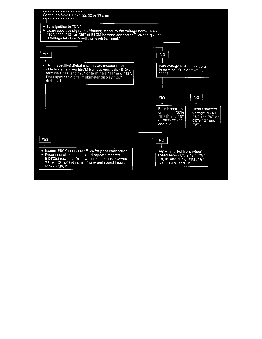
INSPECTION PROCEDURE
CIRCUIT DESCRIPTION:
DTCs 21 and 22
As a toothed ring passes by the wheel speed sensor, changes in the electromagnetic field cause the wheel, speed sensor to produce a sinusoidal (AC)
voltage signal whose frequency is proportional to wheel speed. The magnitude of this signal is directly related to wheel speed and the proximity of the
wheel speed sensor to the toothed ring (often referred to as the air gap).
DTCs 32 and 33
The toothed wheel generates a voltage pulse as it moves past the sensor; each tooth-gap-tooth series on the wheel generates these pulses. The
frequency of these pulses in used by the Electronic Brake Control Module (EBCM) to determine wheel speed. The amount of voltage generated in
each pulse depends on the air gap between the sensor and the toothed wheel, and on wheel speed.
FAILURE CONDITION:
DTCs 21 and 22 can be set when the vehicle is not in an Antilock Brake System (ABS) stop. If the left front wheel speed is less than 1/2 of the
vehicle's reference speed and the vehicle's reference speed is greater than 8 km/h (5 mph) function exists.
DTCs 32 and 33 can be set anytime. If the EBCM detects an open or short to voltage or ground in CKT"BI", "BI/B", "G" or "G/B", a malfunction
exists.
DIAGNOSTIC AIDS:
An "intermittent" malfunction may be caused by a poor connection, rubbed through wire insulation or a wire that is broken inside the insulation.
The frequency of the malfunction can be checked by using the enhanced diagnostic function of the TECH-1, as described in "Enhanced Diagnostics".
If the customer's comments reflect that the "ABS" warning light is on only during moist environmental changes (rain, snow, vehicle wash, etc.), all
wheel speed sensor circuitry should be thoroughly inspected for signs of water intrusion. Use the following procedure:
1) Spray down the suspected area with 5 % salt water solution (10 ml [2 teaspoons] of salt to 355 ml [12 FL.oz.] of water).
2) Start vehicle and allow it to run for ten seconds.
3) If the DTC returns immediately, replace the suspected harness.
Any circuitry that is suspected of causing the intermittent malfunction should be thoroughly checked for backed out terminals, improper mating,
broken locks, improperly formed or damaged terminals, poor terminal-to-wiring connections or physical damage to the wiring harness.
