
Sidekick JS 2D Soft Top 2WD L4-1.6L (1997)
Wheel Speed Sensor: Component Tests and General Diagnostics
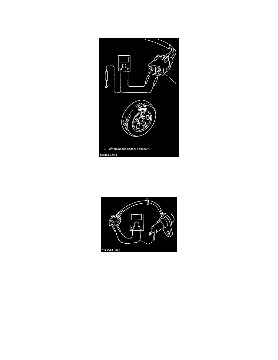
1. Turn ignition switch "OFF".
2. Hoist vehicle a little.
3. Disconnect connector of wheel speed sensor and check the sensor for damage.
4. Connect voltmeter between connector terminals.
5. While turning the wheel at a speed of approximately 2/3 to 1 full rotation per second, check AC voltage of the sensor. Output AC voltage should
be 106 mV or more @ (35 - 53 Hz).
NOTE: When using oscilloscope for this check, check if peak-to-peak voltage meets specifications and the waveform is complete. Peak-to-peak
voltage at 2/3 to one rotation per second is 150 mV or more @ (35 - 53 Hz).
6. Resistance between the two terminals should be 1200 -1600 ohms at 20°C (68°F).
7. Resistance between terminal and sensor body should be 1 M ohm or more.
8. If measured voltage or resistance is not as specified, check sensor, rotor and their installation conditions and replace as necessary.