
Sidekick JS 2D Soft Top 2WD L4-1.6L (1997)
connecting rod and piston assembly.
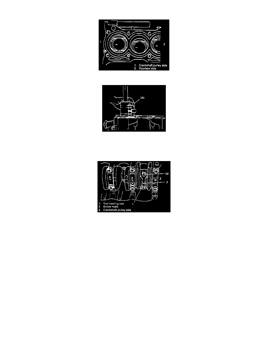
3. When installing piston and connecting rod assembly into cylinder bore, point arrow mark on piston head to crankshaft pulley side.
4. Install piston and connecting rod assembly into cylinder bore. Use special tool (Piston ring compressor) to compress rings. Guide connecting rod
into place on crankshaft. Using a hammer handle, tap piston head to install piston into bore. Hold ring compressor firmly against cylinder block
until all piston rings have entered cylinder bore.
Special Tool (A): 09916-77310 or equivalent.
5. Install bearing cap: Point arrow mark on cap to crankshaft pulley side. Tighten cap nuts to specification.
Tightening Torque (a): 35 Nm (3.5 kg-m, 25.5 ft. lbs.)
6. Reverse removal procedure for installation, as previously outlined.
7. Adjust water pump drive belt tension.
8. Adjust power steering pump belt tension or A/C compressor belt tension, if equipped.
9. Adjust accelerator cable play and Automatic Transmission (A/T) kickdown cable.
10. Check to ensure that all removed parts are back in place. Reinstall any necessary parts which have not been reinstalled.
11. Refill engine with engine oil.
12. Refill cooling system.
13. Refill front differential housing with gear oil.
14. Connect negative cable at battery.
15. Check ignition timing and adjust as necessary.
16. Verify that there is no fuel leakage, coolant leakage, oil leakage and exhaust gas leakage at each connection.