
Sidekick JS 2D Soft Top 2WD L4-1.6L (1997)
7. Using special tool (Valve guide remover), drive valve guide out from combustion chamber side to valve spring side.
Special Tool (A): 09916-44910 or equivalent.
NOTE: Do not reuse valve guide once disassembled. Be sure to use new valve guide (Oversize) when assembling.
8. Place disassembled parts except valve stem seal and valve guide in order, so that they can be installed in their original position.
ASSEMBLY
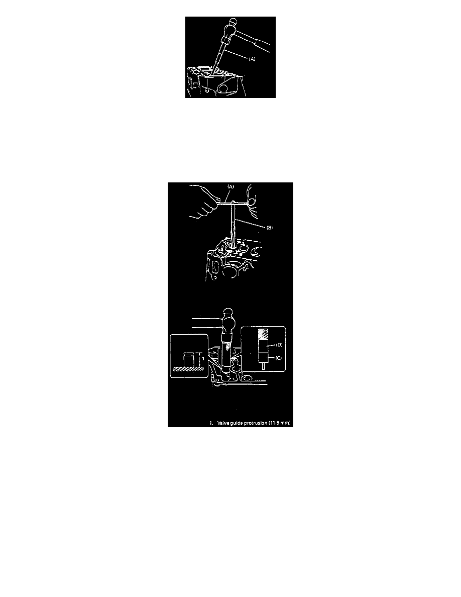
1. Before installing valve guide into cylinder head, ream guide hole with special tool (11 mm reamer) so remove burrs and make it truly round.
Special Tool:
(A): 09916-34541 or equivalent.
(B): 09916-38210 or equivalent.
2. Install valve guide to cylinder head. Heat cylinder head uniformly at a temperature of 80 to 100°C (176 to 212°F) so that head will not be
distorted, and drive new valve guide into hole with special tools. Drive in new valve guide until special tool (Valve guide installer) contacts
cylinder head. After installing, make sure that valve guide protrudes by 11.5 mm (0.45 inch) from cylinder head.
Special Tool:
(C): 09916-56011 or equivalent
(D): 09916-58210 or equivalent
Valve Guide Oversize: 0.03 mm (0.0012 inch)
Valve Guide Protrusion (Intake and Exhaust): 11.5 mm (0.45 inch).
NOTE:
^
Do not reuse valve guide once disassembled. Install new valve guide (Oversize)
^
Intake and exhaust valve guides are identical