
Sidekick JS 2D Soft Top 2WD L4-1.6L (1997)
HOW TO READ SYSTEM CIRCUIT DIAGRAM
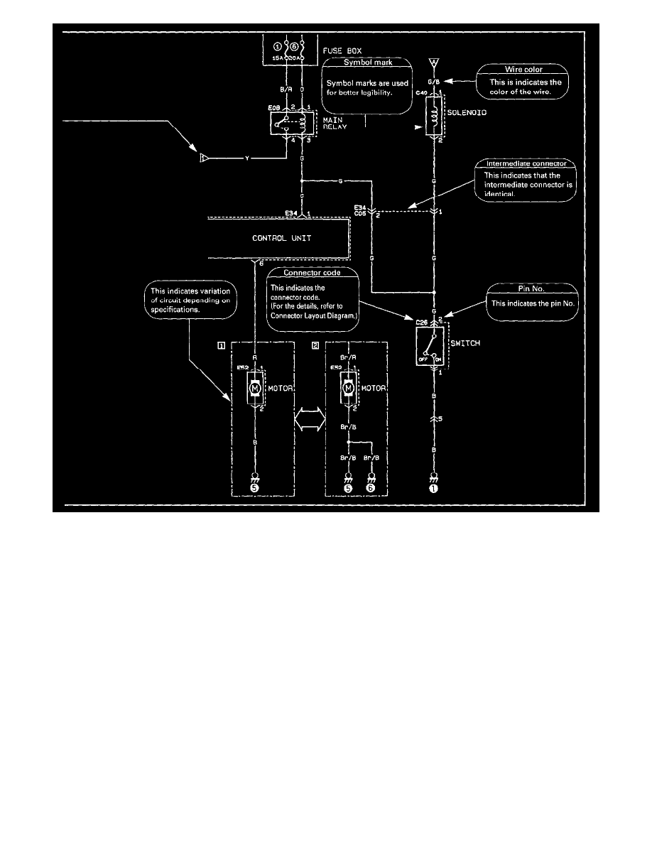
The circuit diagram of each system shows the electric circuit from the main fuse, fuse box or the ignition switch (at the top in the diagram) to the
ground (at the bottom) so that the circuit can be followed easily when performing inspection and service work. For utilization of this diagram together
with Connector Layout Diagram or List of Connectors (shape of connector/pin arrangement).
Indication of Connectors and How to Read Them
INDICATION OF CONNECTORS AND HOW TO READ THEM
The connectors are indicated as shown below in System Circuit Diagram. For the shape and pin arrangement of each connector used, refer to
Connector Views. Described below are how they are indicated and how to read them.
1.
-
The male terminal and female terminal are identified by a double enclosure and a single one respectively.
-
The intermediate connector which connects harnesses is shown by both shapes of the male terminal and the female terminal but the connector
to be connected directly to the equipment is shown by the shape of the connector on the harness side.