
Sidekick JS 2D Soft Top 2WD L4-1.6L (1997)
The new shift lock solenoid assembly is shipped from the factory with the release cam held into place by the lock pin. Do not remove the lock pin in
this step.
2.
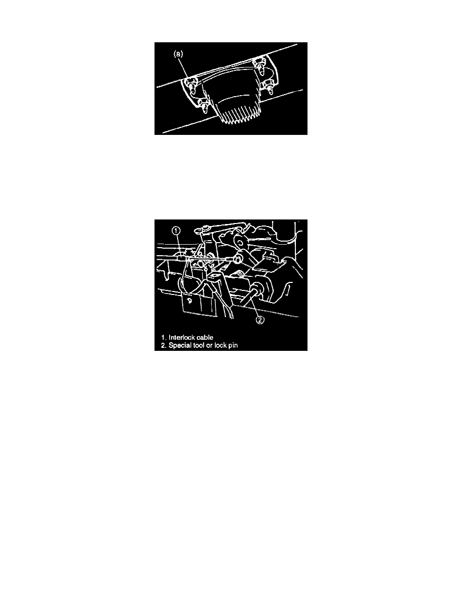
Tighten the housing nut to the specified torque.
Tightening Torque
(a): 13.5 - 15.5 lb-ft (18-22 N.m, 1.8-2.2 kg-m)
3.
Connect the select cable end to the selector assembly lever.
4.
With the lock plate moved towards the front of the vehicle, shift the selector lever to the "N" position.
5.
Align the release cam by inserting the lock pin or a special tool into the holes in the cam and solenoid bracket. Refer to step 4. of "Brake (key)
Interlock Cable Installation."
6.
Connect the cable end to the key release cam referring to step 5. and 6. of "Brake (Key) Interlock Cable Installation."
7.
Remove the special tool or lock pin from the key release cam.
8.
Make sure that the key release cam and interlock cable operate properly, referring to steps 7-10 in the "Interlock Cable Installation" section.
9.
Reconnect the electrical connectors to the shift solenoid and illumination lamp.
10.
Reinstall the select indicator and center console.
11.
Reconnect the negative cable to the battery.
12.
Check that the brake (key) interlock system is operating properly.