
Sidekick JS 2D Soft Top 2WD L4-1.6L (1997)
Electronic Brake Control Module: Testing and Inspection
CAUTION: When connectors are fastened to the ABS control module, do not disconnect the sensors, relay, fuse etc. of the hydraulic unit, and turn
ignition switch "ON." Then the Diagnostic Trouble Codes (DTC) will be set in the ABS control module.
NOTE: Check hydraulic unit for fluid leakage. If any, repair or replace.
1. Check that basic brake system other than ABS is in good condition.
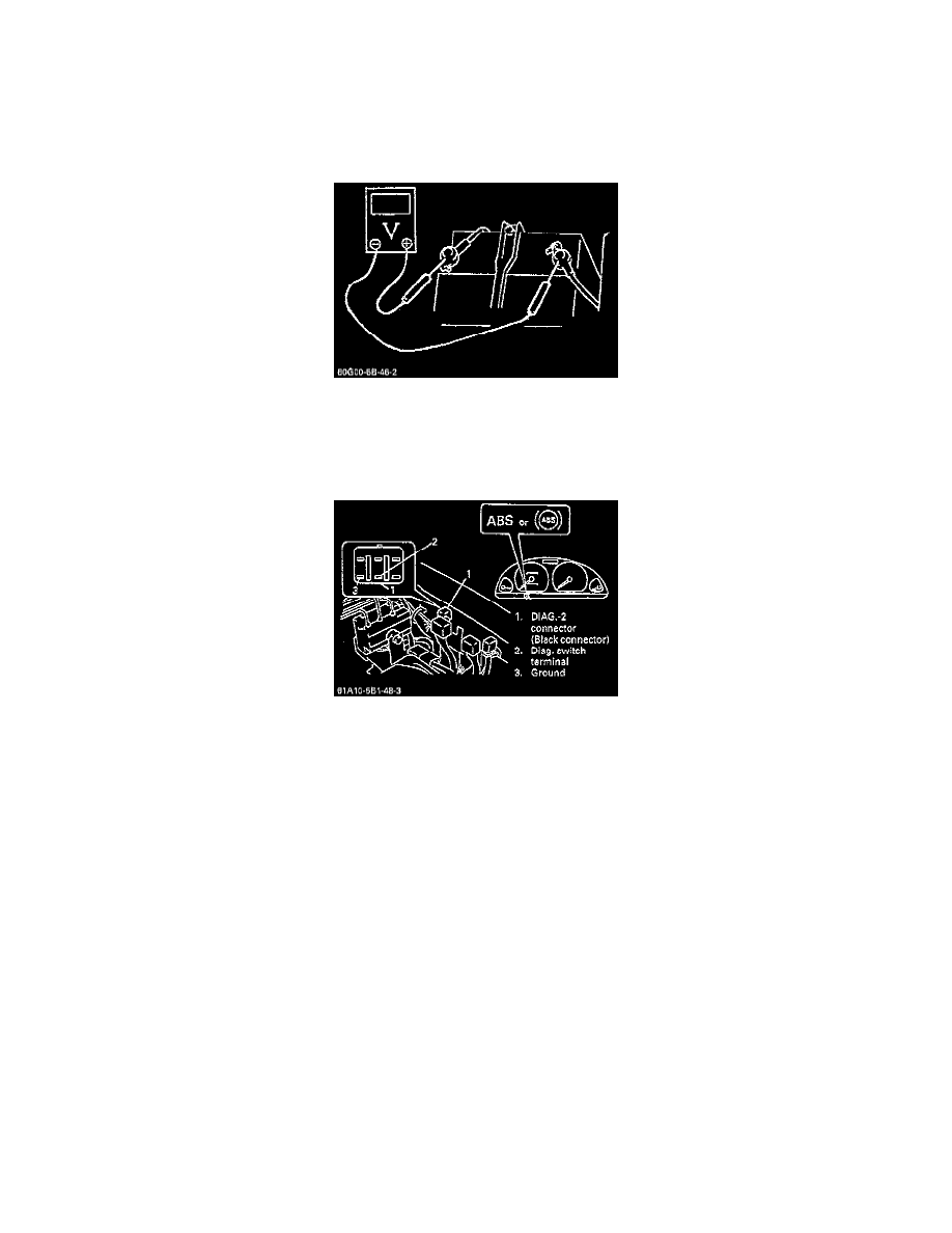
2. Check that battery voltage is 11 volts or higher.
3. With the ABS warning lamp, check that no abnormality is detected in the ABS.
4. Lift vehicle.
5. Set transmission to neutral and release parking brake.
6. Turn each wheel gradually by hand to check if brake dragging occurs. If it does, correct.
7. With diagnostic switch terminal of DIAG.-2 connector connected to ground (by using service wire,) turn the ignition switch "ON" and check if the
ABS warning lamp indicates DTC 12.
8. Turn ignition switch "OFF".
9. The brake pedal should be depressed and the ignition switch turned "ON" by one person and the wheel should be turned by another person. Check
that the operation sound of the solenoid is heard and that the wheel turns only about 0.5 second. (Brake force is re-pressurized). Make sure the
operational sound of the pump motor is heard and the pulsation is felt at brake pedal.
10
.If all 4 wheels cannot be checked during one ignition cycle (OFF-ON), repeat Step 8 and 9 till all 4 wheels are checked. If a faulty condition is
found in Steps 9 and 10, replace the hydraulic unit.
11. Turn ignition switch "OFF" and remove the service wire from DIAG.-2 connector.