
Sidekick JS 2D Soft Top 2WD L4-1.6L (1997)
(A): 09925-78210 (6 mm)
5.
Connect the cable end to the key release cam.
6.
With the cable bracket pushed in the direction of the arrow by spring force, tighten the cable bracket bolt.
Tightening Torque
4(b): 4.0 - 5.0 lb-ft (5 - 7 N.m, 0.5 - 0.7 kg-m)
7.
Remove the special tool and turn the ignition switch the "ACC" position.
8.
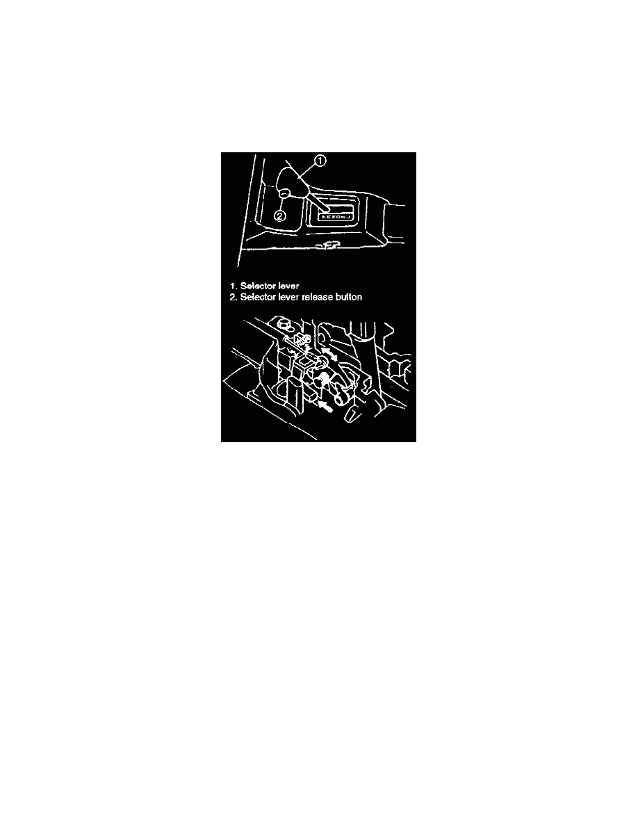
With the selector lever in the "P" position and the shift lock solenoid lock plate moved towards the front of the vehicle, check that the key release
cam moves smoothly by depressing the selector lever release button.
9.
With the selector lever in the "P" position, turn the ignition key to the "ACC" position. Make sure that the ignition key can be turned from the
"ACC" position to the "LOCK" position.
10.
With the selector lever in the "P" position, grab hold of the selector lever and depress the selector lever release button. Make sure that the ignition
key cannot be turned from the "ACC" position to the "LOCK" position.
11.
Install the steering column, referring to Section 3C1 in the service manual.
12.
Install the steering column hole cover and steering joint cover.
13.
Reconnect the negative cable to the battery and enable the air bag system, referring to "ENABLING AIR BAG SYSTEM" in Section 9J of the
service manual.
ADJUSTMENT
1.
Remove the center console and loosen the cable bracket bolt.
2.
Turn the ignition key to the "ACC" position.
3.
Adjust the cable according to steps 3-4 and 6-10.
Manual Selector Assembly
REMOVAL
1.
Disconnect the negative cable from the battery.
2.
Remove the center console.