
Sidekick JX 4D Hard Top 4WD L4-1.6L (1997)
3.
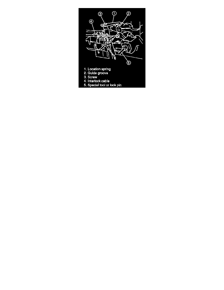
Align the location spring end with the guide groove and tighten the spring screw securely.
4.
Apply grease to the guide grooves and detent pin.
5.
If the lock pin was removed, align the release cam by inserting the lock pin or a special tool into the holes in the cam and solenoid bracket. Refer
to step 4. of the "Brake (Key) Interlock Cable Installation" section.
6.
Connect the interlock cable end to the cam, referring to step 5. and 6. of the "Brake (Key) Interlock Cable Installation."
7.
Remove the lock pin or special tool from the key release cam.
8.
Check that the key release cam and interlock cable are operating properly, referring to step 7. and 8. of the "Interlock Cable Installation."
9.
Reconnect the electrical connectors to the shift solenoid and illumination lamp.
10.
Reinstall the select indicator and center console.
11.
Reconnect the negative cable to the battery.
12.
Check that the brake (key) interlock system is operating properly.
Brake (Key) Interlock Cable
NOTE:
Use care when removing the interlock cable. Excessive bending of the cable will cause the system to malfunction.
REMOVAL
1.
Disconnect the negative cable from the battery and disarm the air bag system, referring to the section entitled, "DISABLING AIR BAG SYSTEM"
on Section 9J of the service manual.
2.
Remove the steering column hole cover and steering joint cover.
3.
Disconnect the steering shaft upper joint bolt and steering column mounting bolts and nuts.
CAUTION:
Make sure that the top bolts of the steering shaft joint are tight before loosening the steering column mounting bolts and/or nuts. Otherwise, damage
to the shaft joint bearing may occur.