
Swift L4-1298cc 1.3L DOHC 3 MFI 16V (1989)
3.
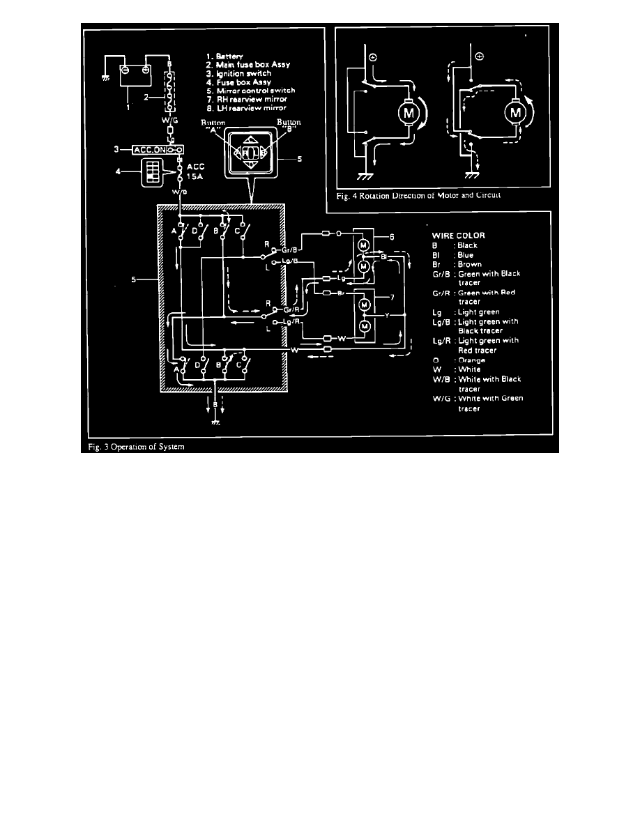
Operation of System (Figure 3)
1.
Location of System Components
The electric power mirror control system consists of the mirror control switch, motors built in the motor and related wiring harness. With this system, it
is possible to control the rearview mirrors, (right and left) in both up/down and right/left directions within a certain angle range.
2.
System Wiring Diagram
3.
Operation of System
Figure 3 shows the electrical power mirror control system circuit. The operation of buttons A, B, C and D of the mirror control switch correspond
directly with the operation of switches A, B, C and D located within the switch's circuitry. Therefore, if button A of the mirror control switch is
depressed switch A of the control switch circuit closes causing the mirror to operate toward the left direction as shown by the solid arrow line. Similarly,
when the B button is depressed, switch B of the control swith circuitry closes causing the mirror to operate toward the right direction as shown by the
broken arrow line.
The rotation direction of the motor is controlled by the direction of the electric current flowing to the motor which varies depending on which mirror
control switch button is depressed. Fig 4 shows the circuits forrned when the motor runs clockwise and counterclockwise respectively.