
Swift L4-1298cc 1.3L DOHC 3 MFI 16V (1989)
e. Remove housings. Using scale on gaging plastic envelop, measure gaging plastic width at its widest point Fig. 23. If measured camshaft
journal clearance exceeds .0047 inch, measure journal housing bore Fig. 24, and outside diameter of camshaft journal Fig. 25. If journal
housing bore is not within 1.1024-1.1032 inches, replace cylinder head assembly. If outside diameter of camshaft journal is not within
1.1007-1.1015 inches, replace camshaft.
Hydraulic Valve Lash Adjuster Wear
1.
Inspect adjuster for pitting, scratches or damage, replace if any malcondition id found.
2.
Measure adjuster outside diameter. If measured diameter exceeds 1.2188-1.2194 inches, replace adjuster.
3.
Measure cylinder adjuster bore. If measured bore diameter exceeds 1.2205-1.2214 inches, replace cylinder head.
INSTALLATION
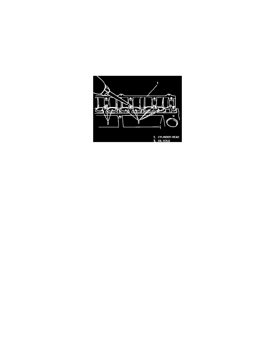
Fig. 26 Checking Oil Passages
1.
Pour engine oil through camshaft journal oil holes. Ensure oil comes out of oil holes in valve lash adjuster bores, Fig. 26.
2.
Lubricate and install valve lash adjusters.
3.
Lubricate and install camshafts. Camshaft pulley pin hole must be at bottom center position.
4.
Install camshaft housings as follows:
a. Lubricate sliding surfaces of each housings.
b. Apply sealant No. 99000-31110 or equivalent, to mating surface of IN 1 and EX 1 housings and cylinder head.
c. Install housings on correct journals, Fig. 21. Camshaft housing IN 1 or EX 1 retains camshaft in proper position as to thrust direction. Securely
fit these housings to respective No. 1 journals first.
d. Tighten housing bolts evenly in a four step procedure in sequence shown in Fig. 22, until specified torque is reached.
5.
Lubricate and press fit camshaft oil seal until oil seal surface becomes flush with housing surface.
6.
Install pins to each camshaft, then install camshaft timing belt pulleys. Pin for intake pulley must be in slot marked I. Pin for exhaust pulley must
be in slot marked E.
7.
Reverse removal procedure to complete assembly, noting the following:
a. Tighten all bolts to specifications.
b. Do not turn camshafts or start engine for 30 minutes after reinstalling hydraulic valve lash adjusters and camshafts.
c. If air is trapped in valve lash adjuster, valve may make tapping sound when engine is operated. In such cases, run engine for 30 minutes at
2,000 RPM, this will purge air from adjuster. If tapping is still present, a possible defective adjuster is present, replace defective adjuster.