
Swift L4-1298cc 1.3L DOHC 3 MFI 16V (1989)
Throttle Position Sensor: Adjustments
Throttle stop screw is factory preset, do not remove or adjust.
1.
Disconnect battery ground cable, then TPS coupler.
2.
Loosen TPS screws.
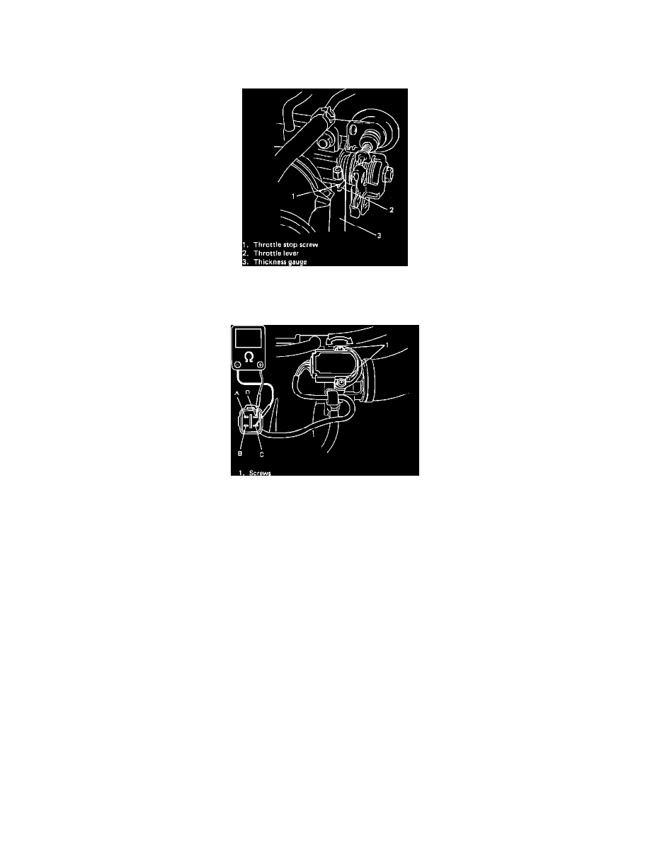
Fig. 81 Inserting Thickness Gauge
3.
Insert .025 inch thickness gauge between throttle stop screw and throttle lever, Fig. 81.
Fig. 82 Adjusting TPS
4.
Connect ohmmeter between C and D terminals of TPS connector, Fig. 82.
5.
Turn TPS clockwise fully, then counterclockwise gradually to find position where ohmmeter reading changes from zero to infinite. Tighten TPS at
that position.
6.
Ensure there is no continuity between terminal C and D when .035 inch thickness gauge is inserted between stop screw and throttle lever.
7.
Ensure there is continuity between terminal C and D when .012 inch thickness gauge is inserted between stop screw and throttle lever.
8.
If checks in step 6 and 7 are not as specified, installation angle of TPS is not adjusted properly. Repeat complete procedure.
9.
Connect coupler to TPS and battery ground cable.