
Swift L4-1298cc 1.3L SOHC MFI (1997)
Vacuum Brake Booster: Description and Operation
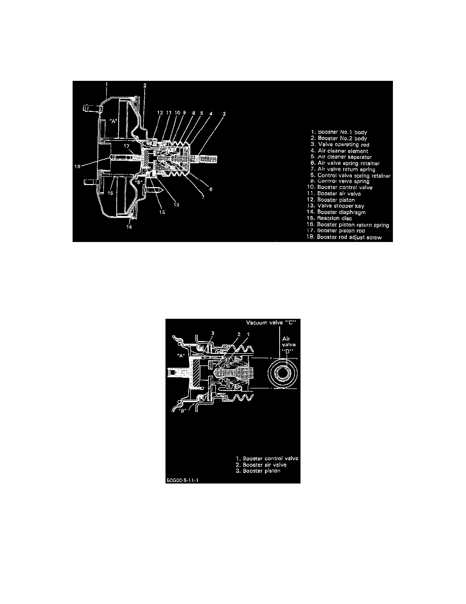
GENERAL INFORMATION
The booster is located between the master cylinder and the brake pedal. It is so designed that the force created when the brake pedal is depressed is
mechanically increased combined with the engine vacuum. The booster has a diaphragm of 180 mm (7 inches) effective diameter.
CAUTION: When and after removing booster, never drop, deform or disassemble it.
OPERATION
When the brake pedal is depressed, the force is transmitted to the piston of the master cylinder through the valve operating rod, booster air valve,
reaction disc, and piston rod. At the same time, the force of the booster piston developed due to the pressure difference between the two chambers
"A" and "B" in the above image is added to it. The end of the booster control valve has a double function of a vacuum valve and air valve. That is,
as shown in the above image, the booster control valve closes between the "A" and "B" chambers as its outer end "C" contacts the booster piston
seat and opens as "C" leaves the booster piston seat (vacuum valve function). Also it closes between the "B" chamber and outside air as its inner
end "D" contacts the air valve seat and opens as "D" leaves the air valve seat (air valve function).
When Foot Brake Pedal Is Not Depressed
The valve operating rod is pushed to the right by the spring force as shown. The air valve is also enough to the right to contact the valve stopper
key as shown. In this state, the vacuum valve (control valve "C") is open and the air valve (control valve "D") is closed. Thus the chambers "A"
and "B" conduct and share the same negative pressure (because of no pressure difference) which allows the return spring to push the booster piston
to the right.