
Swift GA L4-1298cc 1.3L SOHC MFI (2001)
4. Using continuity check or voltage check procedure described, check the wire harness for open circuit and poor connection with its terminals.
Locate abnormality, if any.
Continuity Check
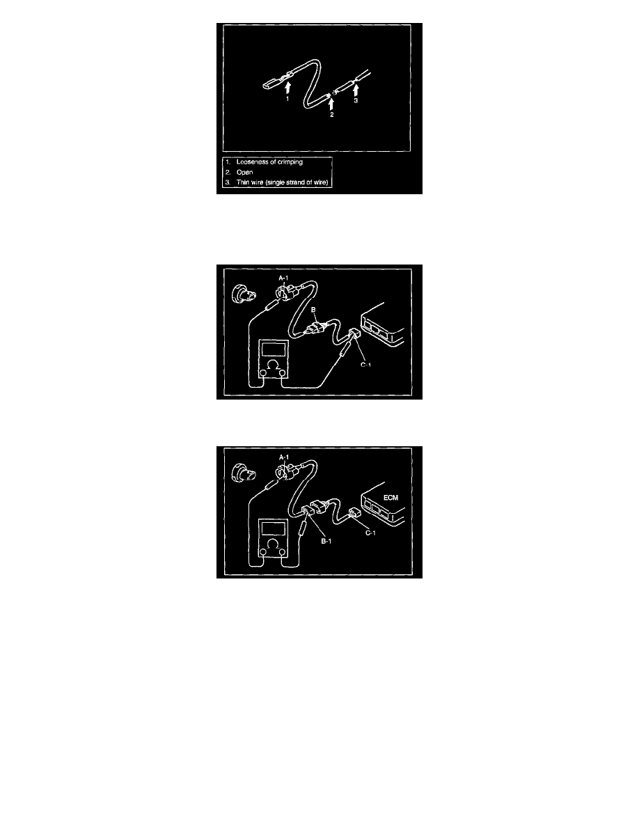
1. Measure resistance between connector terminals at both ends of the circuit being checked (between A-1 and C-1 in the figure). If no continuity is
indicated (infinity or over limit), that means that the circuit is open between terminals A-1 and C-1.
2. Disconnect the connector included in the circuit (connector-B in the figure) and measure resistance between terminals A-1 and B-1.
If no continuity is indicated, that means that the circuit is open between terminals A-1 and B-1. If continuity is indicated, there is an open circuit
between terminals B-1 and C-1 or an abnormality in connector-B.