
SX4 4WD L4-2.0L (2008)
Oxygen Sensor: Description and Operation
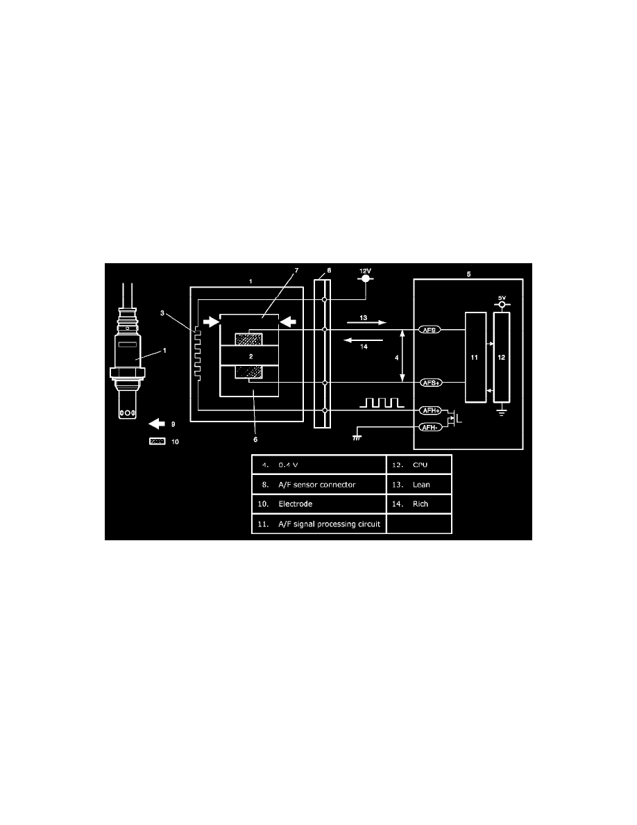
A/F Sensor Description
A/F sensor (1), in place of the conventional HO2S-1, is installed in the center of the exhaust manifold joining section and it consists of a zirconia element
(2) which causes the output current to vary according to difference in the oxygen concentration and a heater (3) which activates the element.
A/F sensor detects oxygen concentration in exhaust gas (9) (A/F ratio of the air-fuel mixture) linearly, ranging from LEAN to RICH.
Operation
ECM (5) controls the sensor heater (3) and keeps the sensor element temperature at the specified level (about 750 °C) constantly so that the A/F sensor is
activated in the specified way for accurate A/F detection. When the sensor element reaches the specified temperature (it is activated), its impedance
drops to the specified value (approx. 30 ohms) by its characteristic. When a certain voltage (about 0.4 V) is applied between sensor elements in this
state, circuit current corresponding to the sensor element impedance flows in the sensor circuit. ECM detects this circuit current and judges whether the
sensor is in the active state or not. At this time, sensor current is output linearly in the range of +0.01 mA to +some mA on the lean side and -0.01 mA to
-some mA on the rich side. The variation in these ranges depends on the difference from the stoichiometry A/F ratio, that is, the amount of oxygen
between the atmosphere side and exhaust manifold (7).
According to this sensor output, ECM executes A/F feedback (fuel trim) to achieve the target A/ ratio.