
Verona L6-2.5L (2005)
Hydraulic Control Assembly - Antilock Brakes: Service and Repair
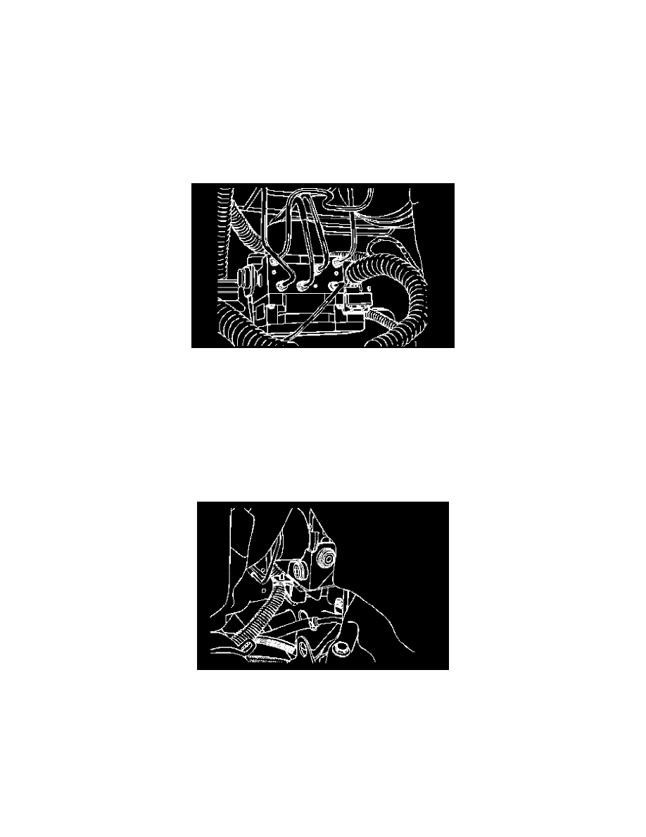
EBCM Assembly Removal and Installation
CAUTION: Do not hang the caliper assembly from the brake hose. Any resulting internal hose restriction will impede uniform braking action.
CAUTION: To guarantee uniform braking on both sides, both rotors must have identical surfaces regarding smoothness and scoring depth. For this
reason always replace both rotors.
Removal
1) Disconnect the negative battery cable.
2) Removed the cooling surge tank.
3) Disconnect the ABS wiring harness connector from its socket on the EBCM.
4) Cover the connector and the socket with shop cloths to protect them from brake fluid.
5) Remove the brake pipes fitting nuts from the hydraulic unit.
NOTE: Take care not to allow air into the hydraulic unit or into the brake pipes from the master cylinder. If air gets into the hydraulic unit, it will
require a bleeding procedure using a scan tool programmed for the MGH-25 ABS system. As long as no air enters the hydraulic unit, a simple
bleeding procedure is all the system will require.
6) Remove the mounting bracket bolts on the hydraulic unit.
7) Remove the EBCM assembly.
Installation Notice
Tighten:
Tighten the torque brake pipe fitting nuts to 16 Nm (12 ft. lbs.)
Tighten:
Tighten the EBCM mounting bracket Bolts to 22 Nm (16 ft. lbs.)
^
Add new brake fluid.
^
After the installation, bleed the brake system.
^
Check the brake system for leaks.
^
Care must be taken to prevent the brake fluid from contacting any painted surface to prevent damage to the paint finish.