
Verona L6-2.5L (2005)
that there is no dirt between the rotor and the hub and that hub-to-rotor contact surfaces are smooth and free from burrs. Use a commercially available
dial indicator to check the lateral runout according to the following procedure.
1. Position the transaxle in NEUTRAL and raise the vehicle.
2. To preserve wheel balance, mark the relative positions of the wheel and hub, and remove the rear wheel.
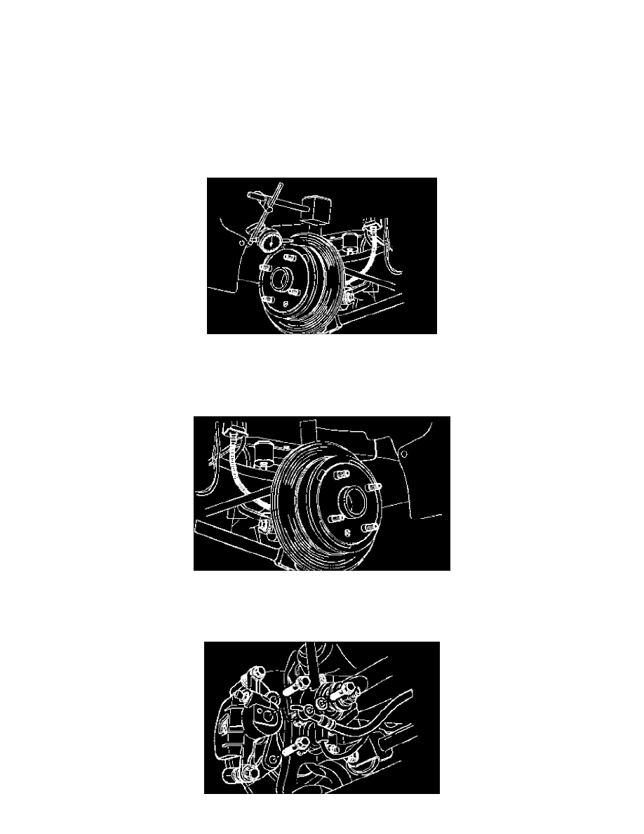
3. Fasten the brake rotor to the wheel hub.
4. Mount a dial indicator on the brake caliper.
5. Place the indicator tip approximately 10 mm (0.39 inch) from the outer edge of the brake rotor, perpendicular to the disc and under slight
preload. Observe the indicator gauge while rotating the rotor.
6. After measuring is completed, remove the dial indicator and the wheel nuts.
7. If necessary, refinish the rotor with precision equipment. Measure the runout again after refinishing. If the runout exceeds 0.8 mm (0.03 inch)
after refinishing, the rotor should be replaced.
8. Align the marks that were made before wheel removal, and install the rear wheel.
9. Lower the vehicle.
Rotor Installation
CAUTION: To guarantee uniform braking, always refinish both rotors even if only one rotor is defective.
1. Install the rotor on the front wheel hub and install the detent screw.
Tighten: Tighten the rotor detent screw to 4 Nm (35 inch lbs.)
2. Apply a few drops of thread-locking compound to the caliper bracket mounting bolts and install the caliper bracket.
Tighten: Tighten the caliper bracket mounting bolts to 45 Nm (33 ft. lbs.).