
Verona L6-2.5L (2005)
A/C Coupler O-ring: Service and Repair
Cylinder-to-Front Head O-Ring Removal and Installation
Cylinder-to-Front Head O-Ring Removal and Installation
Cylinder-to-Front Head O-Ring Removal
Tools Required:
J-34993 Cylinder Alignment Rods
J-35372 Support Block
1. Recover the refrigerant. Refer to Discharging, Adding Oil, Evacuating, and Charging Procedures for A/C System.
2. Remove the compressor. Refer to Compressor Installation.
3. Drain the oil from compressor into a suitable container. Measure and record the amount of oil drained from the compressor. Discard all used oil.
4. Remove the clutch plate and hub assembly. Refer to Clutch Plate and Hub Assembly Disassembly.
5. Remove the clutch rotor and bearing. Refer to Clutch Rotor and Bearing Disassembly.
6. Remove the clutch coil. Refer to Clutch Coil Removal.
7. Remove and discard the shaft seal parts. Refer to Shaft Seal Removal.
8. Remove the compressor through-bolts. Remove and discard the gaskets.
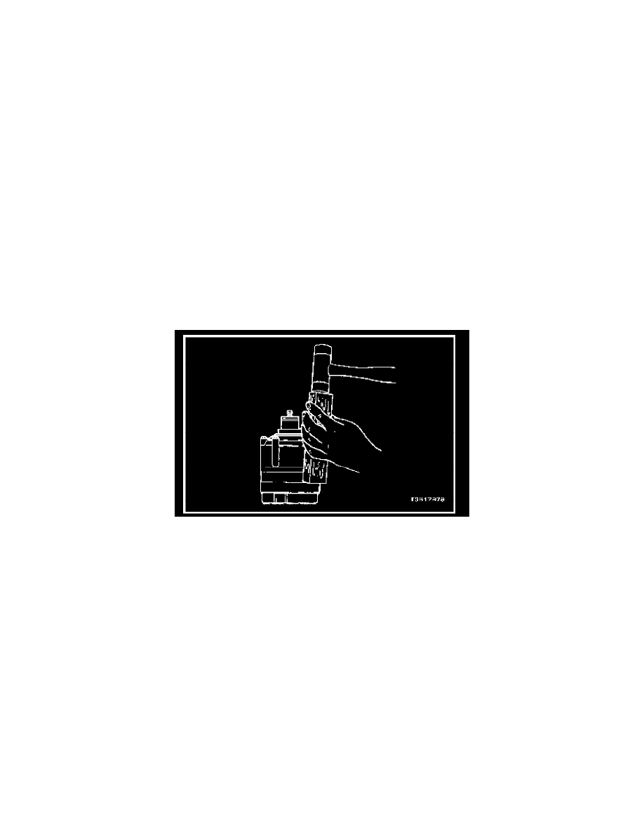
9. Using a wooden block and a plastic-headed hammer, tap the compressor housing at the mounting locations to disengage the housing from the
compressor cylinder.
10. Remove the thrust washer and the bearing.
NOTE: Note the assembly sequence of the thrust washer and bearing for ease of assembly.
11. Remove and discard the compressor housing-to-cylinder O-ring.
Cylinder-to-Front Head O-Ring Installation
1. Rest the rear head on the support block J-35372. Locate the control valve at the 6 o'clock position.
2. Install cylinder alignment rod J-34993 through the 11 o'clock and the 5 o'clock bolt holes.
3. Lubricate the new cylinder-to-compressor housing O-ring with clean polyalkaline glycol (PAG) oil.
4. Install the new O-ring in the cylinder O-ring groove.
5. Install the thrust washer and bearing in the same order as they were removed.
6. Align the guide pin recess in the compressor housing with the guide pin. Press down on the compressor housing with both hands to force it over
the O-ring on the cylinder assembly.
7. Add a new through-bolt gasket to the through-bolts and install it into the compressor assembly. Four through-bolts must thread into the rear head
before removing the guide pins.
Tighten:
Alternately tighten the through-bolts in progressive torque sequence to 10 N.m (89 lb.in).
8. Install a new shaft seal. Refer to Shaft Seal Installation.
9. Add new PAG oil equal to the amount drained in Step 3.
10. Install the clutch coil. Refer to Clutch Coil Installation.
11. Install the clutch rotor and bearing. Refer to Clutch Rotor and Bearing Assembly.
12. Install the clutch plate and hub assembly. Refer to Clutch Plate and Hub Assembly Reassembly.
13. Perform a leak test on the compressor. Refer to Leak Testing Refrigerant System.